
Related Manuals for DART Controls EZ VFD CONTROL Series


Summary of Contents for DART Controls EZ VFD CONTROL Series
- Page 1 CONTROLS Instruction Manual EZ VFD ® Universal AC Input 110 – 240VAC 230VAC / 3Φ Output 800W Phone (317) 873-5211 5000 W. 106th Street Fax (317) 873-1105 Zionsville, Indiana 46077 www.dartcontrols.com LT195 (0221) A-5-4179A...
-
Page 2: Table Of Contents
WARRANTY Dart Controls, Inc. (DCI) warrants its products to be free from defects in material and workmanship. The exclusive remedy for this warranty is DCI factory replacement of any part or parts of such product which shall within 12 months after delivery to the purchaser be returned to DCI factory with all transportation charges prepaid and which DCI determines to its satisfaction to be defective. -
Page 3: Introduction
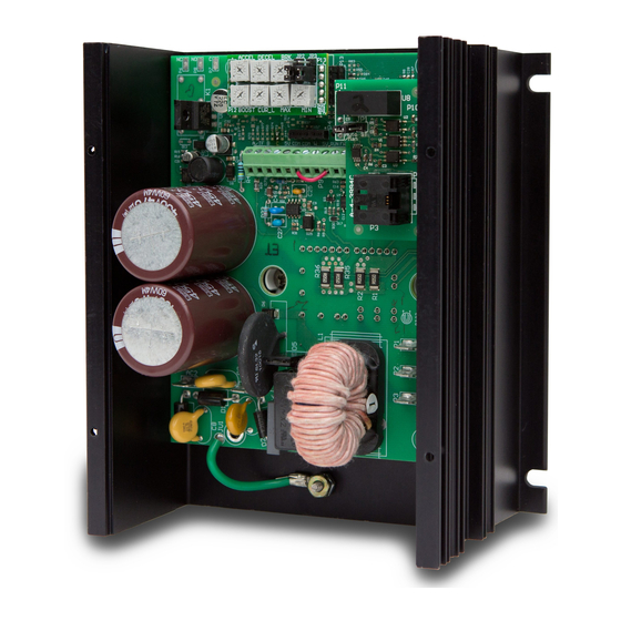
Introduction ® The EZ VFD Series is a volts/Hz variable frequency drive for 3-phase, 230VAC inverter duty AC ® motors. The EZ VFD comes in two styles – open chassis for control panel installation, and a ® stand-alone NEMA 4X enclosed model. The EZ VFD is suited for both constant torque (ex: conveyor, auger) and variable torque (ex: fans, blowers and centrifugal pumps). -
Page 4: Models & Options
Models & Options Models Description VF-100C Open chassis, universal AC input, 230VAC 3 Phase Out, Potentiometer / 0-5VDC follower speed adjustment; MIN, MAX, BOOST, ACCELERATION, DECELERATION, CURRENT LIMIT, BRAKING trimpot adjustments VF-100E NEMA 4X enclosed, universal AC input, 230VAC 3 Phase Out, Potentiometer / 0- 5VDC follower speed adjustment;... -
Page 5: Mechanical Installation
Mechanical Installation Mounting Dimensions Enclosed Dimensions 5.125 TYP. CONTROLS MEM/ FAULT Variable Frequency Drive 5.942 7.150 5.500 5.394 EZ VFD .188 .455 5.530 Chassis Dimensions 6.410 4.114 CAUTION: DO NOT MOUNT WHERE AMBIENT TEMPERATURE IS OUTSIDE THE RANGE OF -10 C (14 F) TO 40 C (104... -
Page 6: Installation & Diagrams
Installation & Diagrams Hookup Diagram MOTOR SPEEDPOT Note: Insulated female quick connects recommended for motor and AC supply connections See P9 Terminal ORANGE Hook-up Ground WHITE FAULT (RED LED) (GREEN LED) -R Option only Enclosed Hook-Up Diagram -R Option only MOTOR Note: Insulated female quick... -
Page 7: P9 Terminal Block Hook-Up Diagram
P9 Terminal Block Hook-Up Diagram P9-11 P9-10 JUMPER REQUIRED TO RUN (shipped this way from factory). P9-9 Remove jumper if remote contacts are used. P9-8 P9-7 CLOSE TO REVERSE CLOSE TO ENABLE P9-11 FWD/REV P9-10 AS REQUIRED BY OPERATOR P9-9 Circuit COM P9-8 P9-11... -
Page 8: Customer Installation, Wiring, & Fusing Requirements
CUSTOMER INSTALLATION, WIRING, & FUSING REQUIREMENTS ® • Do not mount EZ VFD where ambient temperature is outside the range of -10 to 40°C (14 to 104°F). • Installations in unventilated enclosures must be 1.5 times the controller dimensions or more, and the air temperature inside the enclosure and around the controller must remain between 10 to 40°C (14 to 104°F). -
Page 9: Max' Trimpot
'MAX' Trimpot The MAX trimpot range is 48 - 120Hz. The MAX trimpot comes factory set to 60Hz. To decrease the MAX speed setting, turn the trimpot CCW to the desired speed. To increase the MAX speed setting, turn the trimpot CW to the desired speed. Refer to the MAX trimpot diagram for range settings. -
Page 10: Cl' Trimpot
'CL' Trimpot The Current Limit (CL) trimpot is set to 4.8 amps RMS from the factory. A CW rotation of the CL trimpot will increase the CL set point. A CCW rotation of the trimpot will decrease the CL set point. CL should typically be set to 150% of the rated motor phase current. -
Page 11: Basic Operating Information
Active Not exceeded Not exceeded Detected Troubleshooting Technical Support Options • Visit the Dart Controls Web Site at: www.dartcontrols.com • Email technical support at: sales@dartcontrols.com • Telephone technical support at 317-873-5211 What's Special About www.dartcontrols.com? • Changes to printed material and product offerings first appear online •... - Page 12 REPAIR PROCEDURE In the event that a Product manufactured by Dart Controls Incorporated (DCI) is in need of repair service, it should be shipped, freight paid, to: Dart Controls, Inc., 5000 W. 106th Street, Zionsville, IN. 46077, ATTN: Repair Department. Please include Name, Shipping Address (no P.O.
Need help?
Do you have a question about the EZ VFD CONTROL Series and is the answer not in the manual?
Questions and answers