
Related Manuals for DART Controls 530B Series


Summary of Contents for DART Controls 530B Series
- Page 1 CONTROLS Instruction Manual Variable Speed DC Control P.O. Box 10 Phone (317) 873-5211 5000 W. 106th Street Fax (317) 873-1105 Zionsville, Indiana 46077 www.dartcontrols.com LT530B (0505) A-5-3271B...
-
Page 2: Table Of Contents
WARRANTY Dart Controls, Inc. (DCI) warrants its products to be free from defects in material and workmanship. The exclusive remedy for this warranty is DCI factory replacement of any part or parts of such product which shall within 12 months after delivery to the purchaser be returned to DCI factory with all transportation charges prepaid and which DCI determines to its satisfaction to be defective. -
Page 3: Introduction
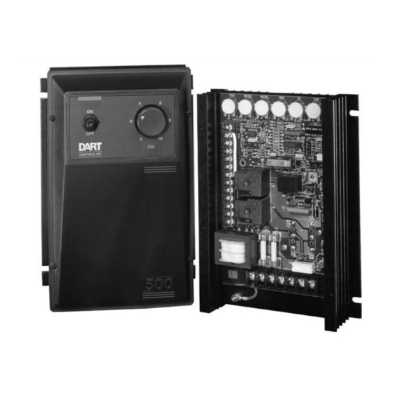
INTRODUCTION The 530B Series is a high performance, dual voltage versatile DC motor control which provides a wide range of standard features, with many options that extend its capabilities. The 530B Series will operate 1/8 through 1.0 horsepower at 115VAC input, and 1/ 4 through 2.0 horsepower at 230VAC input. -
Page 4: Control Features
CONTROL FEATURES INPUT VOLTAGE SELECTION SWITCH - Switch selectable between 115 VAC and 230 VAC input. MIN SPEED - (Minimum speed) Allows adjustment of the motor speed when the speedpot is set at minimum. This permits the user to eliminate the “Deadband” on the main speed control, permitting zero calibration. Clockwise rotation of the “MIN” trimpot increases output VDC. -
Page 5: Speedpot Mounting Dimensions
MOUNTING INSTRUCTIONS 1. Four 7/32" slots are provided for control mounting. 2. The 530B Series chassis can be used as a template. 3. Use standard hardware to mount. 4. For the “RE” version ONLY: Two 7/8" diameter holes are provided in one endplate to facilitate wiring. This allows for easy connection of 1/2"... -
Page 6: Terminal Strip Wiring - P1
(+ FIELD) - DO NOT use for Permanent Magnet motor. This supplies + Field voltage for a Shunt Wound motor. See chart above for dual voltage Field Wound motors. This output is rated at 1 Amp for 530B series controls and 1.5 Amps for the 533B control. -
Page 7: Setting Input Vac
(P2 wiring continued) P2-7 (REV 1) - REV 1 and REV 2 are identical quick stop inputs. One of them must be held low (to AMP REF) before the control will operate. The two are diode separated to form an “OR” gate. Since -ARM (P1-5) is also low in the system, these two inputs can be wired to the motor side of a reversing switch or relay. -
Page 8: Initial Start-Up
INITIAL START UP 1. Check to see that the 115/230 VAC selection switch is set for the desired input voltage. 2. Recheck all wiring. Accidental grounds, loose or pinched wires on armature or speed potentiometer wires may damage the control when power is applied. 3. -
Page 9: Trimpot Setting Chart
(Adjustment procedure continued) CUR. LIM. Limits DC motor armature current (torque) to prevent damage to the motor or control. The current limit is set for 125% of the rated motor current. Clockwise rotation of this trimpot increases the armature current (or torque produced). -
Page 10: Basic Hook-Up Diagram Without Options
BASIC HOOK-UP DIAGRAMS WITHOUT OPTIONS (If options are included on your control, see the option section of this manual). Model 530BC and 533BC ("C Version") OPTIONAL: +FIELD CUR LIM FOR SHUNT PROVIDES SUPPORT AND TRIGGERING FOR WOUND OPTIONS -FIELD MOTORS ONLY IR COMP -ARM DC MOTOR... -
Page 11: 530Bre Hook-Up Diagram
Model 530BRE ("RE Version") OPTIONAL: +FIELD CUR LIM PROVIDES SUPPORT FOR SHUNT AND TRIGGERING FOR WOUND OPTIONS -FIELD MOTORS ONLY IR COMP -ARM DC MOTOR RELAY +ARM FUSES AC (N) VAC INPUT RELAYS VAC INPUT DECEL AC (L) EARTH GROUND ACCEL INPUT VOLTAGE... -
Page 12: Tachometer Feedback & Follower
“CONTROL MODIFICATIONS” continued TACHOMETER FEEDBACK TACHOMETER FOLLOWER Improves speed regulation to –1/2% of base speed. Allows control output to follow tachometer voltage. P2-9 +TACH P2-4 POT WIPER 6/12 VDC at BASE SPEED (3/7 VDC at 1000 RPM for 1800 RPM MOTOR). TACHOMETER TACHOMETER 12 VDC at FULL SPEED... - Page 13 250/500 IS NEEDED THEN REFER TO THE SETUP PROCEDURE BELOW. (530B SERIES TERMINAL STRIP) JUMPER WIRE (JU2) * This option replaces the speedpot with a 4-20 ma. signal to control speed. The current signal input can be either grounded or ungrounded.
-
Page 14: 11 / -15A Options
-7 Option Factory or Field installed Chassis unit Isolated 4-20 ma. Signal Follower Factory only on Enclosed models with Auto / Manual Switch Available on all models 4 to 20 mA ..-7 Input impedance equals 500Ω or less DO NOT USE TRIMPOT CHART TO ADJUST MIN AND MAX TRIMPOTS ON MAIN BOARD. -
Page 15: 38M Options
Warning: The addition of this option no longer allows for dual voltage operation of the 530B series board. The 115/230 VAC input selector switch (530B series board) must be set for the proper VAC input rating of the -36M/-38M option being used. -
Page 16: In Case Of Difficulty
The addition of this option no longer al- lows for dual voltage operation of the 530B series board. The 115/230 VAC input se- -36M / -38M SPST lector switch (530B series board) must be OPTION SWITCH BOARD set for the proper VAC input rating of the -36M/-38M option being used. -
Page 17: Specifications
SPECIFICATIONS AC INPUT VOLTAGE ........................±10% of rated line voltage ALTITUDE ..........................Up to 7,500 feet above sea level CONTROL OVERLOAD CAPACITY ......................200% for 1 minute DIMENSIONS & WEIGHTS: WIDTH LENGTH DEPTH WEIGHT TYPE ENGLISH 6.70" 9.00" 2.25" 40 oz. 6.70"... -
Page 18: 530B Series Parts Placement & List
530B SERIES PARTS PLACEMENT & LIST ACCEL DECEL I.R. COMP CUR LIM RESISTORS ACTIVE DEVICES 220K 2N4124 P2-1 5K TRIM (MIN) LM78L12 REG. P2-2 LM358 IC 300K LM324 IC 3052 MOC P2-3 4.7K L512F BRIDGE 250K TRIM (ACCEL) P2-4 CAPACITORS P2-5 4.7K... - Page 20 REPAIR PROCEDURE In the event that a Product manufactured by Dart Controls Incorporated (DCI) is in need of repair service, it should be shipped, freight paid, to: Dart Controls, Inc., 5000 W. 106th Street, Zionsville, IN. 46077, ATTN: Repair Department.
Need help?
Do you have a question about the 530B Series and is the answer not in the manual?
Questions and answers