Alesis MICROVERB 4 Reference Manual
Multieffects processor
Hide thumbs
Also See for MICROVERB 4:
- Reference manual (69 pages) ,
- User manual (45 pages) ,
- Supplementary manual (4 pages)
Table of Contents
Advertisement
Quick Links
Advertisement
Table of Contents

Related Manuals for Alesis MICROVERB 4


Summary of Contents for Alesis MICROVERB 4
- Page 1 ALESIS MicroVerb 4 Reference Manual...
-
Page 2: How To Use This Manual
This manual is divided into the following sections describing the various modes of the MicroVerb 4. Though we recommend you take time to read through the entire manual once carefully, those having general knowledge about effects devices should use the table of contents to reference specific functions. - Page 3 MicroVerb 4 Reference Manual...
-
Page 4: Table Of Contents
Your First Session with the MicroVerb 4 ... 7 Unpacking and Inspection ... 7 Basic Connections ... 7 Powering Up ... 8 Setting Levels ... 8 What’s on the Front Panel? ... 8 Auditioning Internal Programs ... 10 Switching Between Preset and User Banks ... 10 Adjusting Effects Mix Levels ... - Page 5 Realtime Modulation Functions ... 38 Troubleshooting... 39 Trouble-Shooting Index ... 39 Re-initializing ... 39 Checking the Software Version ... 39 Maintenance/Service ... 40 Cleaning... 40 Obtaining Repair Service... 40 MIDI Implementation Chart... 42 Specifications ... 43 MicroVerb 4 Reference Manual...
- Page 6 Contents MicroVerb 4 Reference Manual...
- Page 7 MicroVerb 4 Reference Manual...
-
Page 8: Your First Session With The Microverb 4
Mono In, Mono or Stereo Out. Connect a mono cord to the [LEFT/MONO] INPUT of the MicroVerb 4 from a mono source. (The Left input will then feed both inputs.) Connect another mono cord from the [LEFT] OUTPUT of the MicroVerb 4 to an amplification system or mixer input. -
Page 9: Setting Levels
If the Input Meters on the MicroVerb 4 begin to clip (go into the red), turn down the Input level or decrease the volume of the source (instrument, mixer send, etc.). If the MicroVerb 4’s level is causing the mixer or amp to distort, turn the Output Level... - Page 10 MIDI channel (see above). ¥ Edit A/ Edit B Controls. Each Program on the MicroVerb 4 has two parameters which can be adjusted. Depending on the type of Program selected, these might alter Reverb Decay, Chorus Depth, etc. When an Edit knob is adjusted, the new value is briefly shown on the LED Display.
-
Page 11: Auditioning Internal Programs
To instantly switch between the Preset and User banks, press the [BANK] button. Each time you press the [BANK] button, the MicroVerb 4 will toggle back and forth between the Preset and User banks. The display will indicate this by showing a program in the 00-99 (Preset) range or the 100-199 (User) range. -
Page 12: Storing Edited Programs
If you select another Program from memory before storing the edited Program, your changes will also be lost. Although the MicroVerb 4 has two banks (Preset and User), you can only store Programs in the User bank. To store an edited Program: ¿... - Page 13 Chapter 1 – Your First Session with the MicroVerb 4 MicroVerb 4 Reference Manual...
-
Page 14: Connections
AC Power Hookup The MicroVerb 4 comes with a power adapter suitable for the voltage of the country it is shipped to (either 110 or 220V, 50 or 60 Hz). With the MicroVerb 4 off, plug the small end of the power adapter cord into MicroVerb 4’s [POWER] socket and the male (plug) end into a source of AC power. -
Page 15: Typical Applications
When used with a mono source, the MicroVerb 4 is placed between the source and the mixer/amplifier. Although the source may be mono, both the [LEFT/MONO] and [RIGHT] outputs can be connected to the inputs of a mixer/amplifier if stereo processing effects are desired. - Page 16 Dual Mono. Connect two mono cords to the [LEFT] and [RIGHT] inputs of the MicroVerb 4 from two mono sources , and two other mono cords from the [LEFT ] and [ RIGHT] outputs of the MicroVerb 4 to a stereo amplification system or two mixer inputs.
-
Page 17: Interfacing To A Mixing Console
(4, 6 or 8, perhaps), the first two sends are reserved for the cue sends, while the remaining sends are used to feed effects, such as the MicroVerb 4. If you are using a mixer with more than two sends, connect the MicroVerb 4 using post-fader sends. -
Page 18: Using Inserts
Mono In - Stereo Out. If you only want to feed the MicroVerb 4 a mono input, but wish to connect both of its outputs back to the mixer, you will need three 1/4" audio cables. Connect a mono cord from an effect send to the [LEFT] input of the... -
Page 19: Using Main Outputs
If you do not hear any audio after making these connections, swap the input and output cables at the MicroVerb 4, as these may be wired backwards. If the cable is color-coded, usually the red jack represents the send (which connects to the MicroVerb 4’s input) and black is the return (which connects to the output). - Page 20 Main Outputs of the mixing console to the [LEFT/MONO] and [RIGHT] inputs of the MicroVerb 4. The [LEFT] and [RIGHT] outputs of the MicroVerb 4 are then connected to a stereo amplifier, or two input channels of another mixing console (for sub-mixing applications).
-
Page 21: Avoiding Ground Loops
In some cases, a “star grounding” scheme must be used, with the mixer at the center of the star providing the shield ground on telescoping shields, which do NOT connect to the chassis ground of other equipment in the system. MicroVerb 4 Reference Manual... -
Page 22: Midi
Note: It is not necessary to follow step 2 if you intend to only send information to the MicroVerb 4, and do not need to receive information back from it. Example: If you only want to be able to recall Programs using MIDI program change messages, there is no need to connect a cable to the MicroVerb 4’s [OUT/THRU] connector. - Page 23 Make sure that the level of these impulses are at least -6dB on the front panel meters (the third segment up) so that the MicroVerb 4 has sufficient level to trigger from. Tip: High notes work better than low notes when using this feature.
-
Page 24: Overview Of Effects
This decaying action is influenced by the room size, the location of the sound source in the room, the hardness of the walls, and many other factors. The MicroVerb 4 offers the following types of reverberation: Concert Hall (Programs 00-09, 100-109) This is a simulation of a large concert hall. -
Page 25: Stereo Chorus
Finally, the waveform shape of the LFO can be changed from a smooth sine wave, to a more abrupt squarewave to make the pitch detuning more pronounced. Some of the MicroVerb 4’s Choruses have individual LFOs controlling the Left and Right sides, set at different rates. These effects, called True Stereo Choruses, often have a wider stereo image than regular Stereo Chorus effects. -
Page 26: Stereo Flange
Edit A controls the speed of the panning effect and Edit B controls the width of the pan. When using the Auto Pan effect, the MicroVerb 4 should have its effects mix 100% wet with no direct signal mixed in to avoid phase problems. -
Page 27: Rate
After a signal has gone through the delay processing, it is fed back to the delay input. The Feedback control sets what percentage of the signal will go back through the delay. At a setting of 0%, no signal will go back through the delay, so only one delay MicroVerb 4 Reference Manual... -
Page 28: Setting Delay Time Using Tap Tempo
The MicroVerb 4 can also set its Delay Time by playing audio into the Inputs. To set the delay time using this method, hold down the Control Footswitch and play some quick notes into the MicroVerb 4. -
Page 29: Multi Effects Parameters
This is an ideal setup for someone using the MicroVerb 4 with a mixer. By hooking two of the Aux Sends into the Left and Right inputs of the MicroVerb 4, you can use it to provide two discrete effects. Some of the multi effects include:... - Page 30 Overview of Effects – Chapter 3 MicroVerb 4 Reference Manual...
- Page 31 Chapter 1 – Your First Session with the MicroVerb 4 MicroVerb 4 Reference Manual...
-
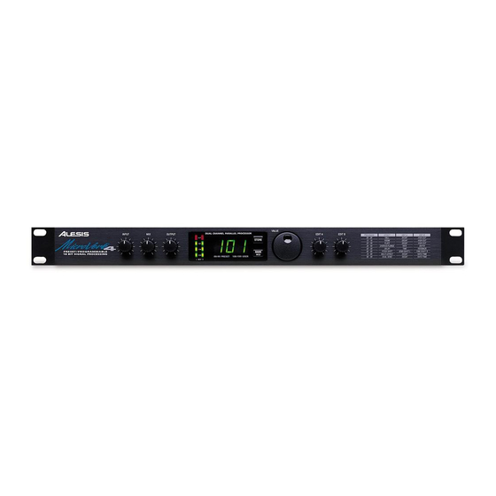
Page 32: Description Of Controls
Front Panel Input Level The Input Level controls the level of the signal being fed into the MicroVerb 4. The MicroVerb 4 can operate with signal levels anywhere from +4dBv Pro Audio gear to guitar level signals. To set the input level, watch the Input Meters while adjusting the Input level (see below). -
Page 33: Store Button
VALUE Knob When no other button is being pressed, the Value Knob is used to change Programs. If the Bank/MIDI button is held while the Value Knob is being turned, the MicroVerb 4 will change its MIDI channel. MicroVerb 4 Reference Manual... -
Page 34: Edit A/Edit B Knobs
Program. For example, on a Concert Hall program, the Edit A knob adjusts Reverb Decay Time and the Edit B knob adjusts Reverb Input Hi Cut. When the Edit A or Edit B knobs are adjusted, the new parameter registers briefly on the display. MicroVerb 4 Reference Manual... -
Page 35: Rear Panel
When one footswitch is plugged into the Footswitch jack, it will function as a Bypass footswitch. When the Footswitch is pressed, the display will read “bYP”, the display will dim, and the MicroVerb 4 will stop producing effects. If the footswitch is pressed again, effects output will continue. -
Page 36: Output (Left & Right)
[LEFT/MONO] input is routed to the [RIGHT] as well. Output (Left & Right) These are 1/4" phone jacks which connect to devices such as the effects returns on a mixing console or Power Amplifier Inputs. For mono applications, use the [LEFT] output. MicroVerb 4 Reference Manual... - Page 37 Chapter 1 – Your First Session with the MicroVerb 4 MicroVerb 4 Reference Manual...
-
Page 38: Midi Functions
Connect the control device’s MIDI OUT to the MicroVerb 4’s [MIDI IN]. ¡ Make sure that the MicroVerb 4 is set to the same MIDI Channel as the device that you are sending from (see above). Note: It is possible to select either the Preset or User bank via MIDI by sending a Controller 0 message immediately followed by a program change message. -
Page 39: Realtime Modulation Functions
The display will read Snd as the User Programs are sent. ¬ When you send a Sysex dump back to the MicroVerb 4, it will automatically go into receive mode (you do not have to do anything to the unit). When this occurs, the display will read rEc. -
Page 40: Troubleshooting
MIDI System Exclusive before performing a re-initialization (see Chapter 6). Checking the Software Version The current software version is displayed when the MicroVerb 4 is powered on. To check the software version, plug in the Microverb 4 and note the number displayed. -
Page 41: Obtaining Repair Service
Chapter 6 – Troubleshooting Disconnect the AC cord, then use a damp cloth to clean the MicroVerb 4’s metal and plastic surfaces. For heavy dirt, use a non-abrasive household cleaner such as Formula 409 or Fantastik. DO NOT SPRAY THE CLEANER DIRECTLY ONTO THE FRONT OF THE UNIT AS IT MAY DESTROY THE LUBRICANTS USED IN THE SWITCHES AND CONTROLS! Spray onto a cloth, then use cloth to clean the unit. -
Page 42: Midi Implementation Chart
MIDI I MPLEMENTATION Function Basic Default * * * * * * * * Channel Changed Default Mode Messages * * * * * * * * Altered Note * * * * * * * * Number True Voice Velocity Note On Note Off... -
Page 43: Specifications
LED Display LED Peak Meters 1/4" 2-conductor 1/4" 2-conductor 1/4" Stereo (accepts normally open or normally closed momentary footswitches, such as the Alesis PD, and Stereo Footswitches) 5 pin DIN 9 Volt Power Transformer (Alesis P3) MicroVerb 4 Reference Manual... - Page 44 Delay memory: Reverb effects: Delay effects: Pitch effects: Special effects: Multiple effect configurations: MicroVerb 4 Reference Manual 24 bit accumulator 1270 milliseconds Concert Hall, Real Room, Ambience, Plate Reverb, Nonlinear Mono Delay, Stereo Delay, Ping Pong Delay, Multi Tap Delay...
Need help?
Do you have a question about the MICROVERB 4 and is the answer not in the manual?
Questions and answers