Konica Minolta PULSOX-2 Instruction Manual
Oxygen saturation monitor
Hide thumbs
Also See for PULSOX-2:
- Specifications (2 pages) ,
- Multi lingual short form instruction manual (28 pages)
Table of Contents
Advertisement
Quick Links
Advertisement
Table of Contents

Related Manuals for Konica Minolta PULSOX-2


Summary of Contents for Konica Minolta PULSOX-2
- Page 1 Oxygen Saturation Monitor PULSOX ™ Instruction Manual...
- Page 2 Safety Symbols Warnings and precautions noted in this manual are indicated by the following mark- ings, designed to prevent accidents caused by erroneous handling of the equipment. This indicates text consisting of a warning or precaution relating to safety. Please read the text carefully and use the equipment safely. This indicates an action which is prohibited.
-
Page 3: Safety Precautions
(Failure to adhere to the following points may result in injury or damage to the instrument or other property.) Do not use batteries other than those specified by KONICA MINOLTA SENS- ING. When installing batteries in the instrument, make sure that they are correctly oriented according to the (+) and (–) marks. -
Page 4: Before Operation
CAUTION: Federal law restricts this device to sale by or on the order of a physician. The PULSOX-2 is a medical instrument, so instructions given by a doctor must be adhered to. The instrument is designed for measurement of the oxygen satu- ration (SpO ) of arterial blood and the pulse rate. -
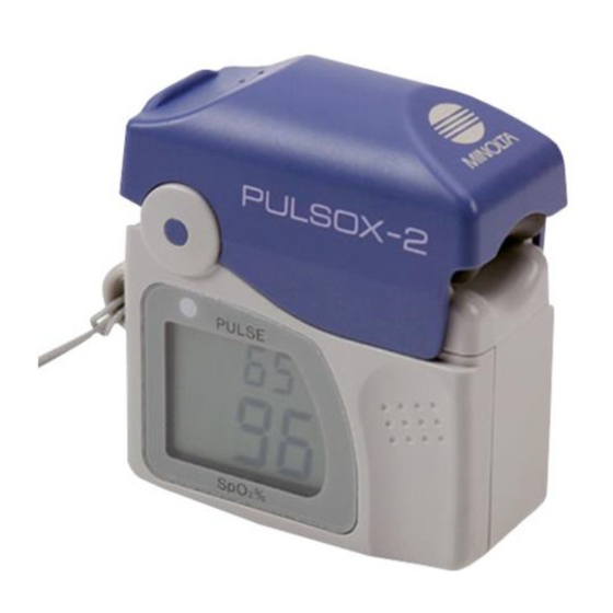
Page 5: Names Of Parts
2. NAMES OF PARTS ■ Main unit Finger holder Battery cover lock Strap eyelet Display Battery cover Thumb rest Battery cover: Open or close this cover when replacing the batteries with new ones. Battery cover lock: It is used to lock the battery cover. Strap eyelet: Attach the neck strap to this hook. -
Page 6: Notes On Use
3. NOTES ON USE • This instrument should be used in areas with an ambient temperature of 0 to 40°C (32 to 104°F) and a relative humidity of 30 to 95%, with no condensation. • This is a precision instrument. To avoid the possibility of it being damaged, the instrument should not be dropped nor should heavy objects be placed on top of it. - Page 7 This equipment has been tested and found to comply with the limits for medical devices to the IEC 60601-1-2:2001, Medical Device Directive 93/42/EEC . These limits are designed to provide reasonable protec- tion against harmful interference in a typical medicitl installation. This equipment generates, uses and can radiate radio frequency energy and, if not installed and used in accordance with the instructions, may cause harmful interference to other devices in the vicinity.
-
Page 8: Operating Method
4. OPERATING METHOD Preparations (1) Installing Batteries (Two AAA-size batteries are required.) 1. Push the battery cover, and unlock the battery cover lock. 2. Open the battery cover. 3. Insert two AAA-size batteries into the battery chamber. 4. Close the battery cover and hold it with a finger. -
Page 9: Installing The Neck Strap
5. Close the battery cover lock until it clicks. • The batteries will last approxi- mately 80 hours. • The battery mark will begin to blink when the battery power is low. Notes on Use • Battery replacement is the Only User Serviceable item. •... - Page 10 Measurements Measurements must be taken with the index finger placed in the finger holder. This instrument must be held tightly. Put the thumb only on the thumb rest. You must not put the thumb on other posi- tions. Don't take the pressure which is unnecessary for the forefin- ger.
- Page 11 Safety Notes This finger holder is designed only for use on the fingers of adults, so it should not be used on any other body parts. Never secure the finger holder with tape or such like. Doing so may cause hemostasia or dropsy. Notes on Use •...
- Page 12 Ending Measurements 1. Open the finger holder and remove the finger. • Measurement will stop automatically, and the display will go off after 10 seconds. Notes on Use • If the instrument will not be used for a long period of time, remove the batteries from the battery chamber.
- Page 13 How to Read the Measurement Values Pulse level meter: Indicates the pulse level in 8 levels (0 to 10%, full scale if 10% or higher). The pulse level is defined as follows. (For sta- ble measurements, adjust the measuring point of the finger holder or rub or warm the measuring point to improve blood circulation, so that the pulse level meter constantly indicates level 2 or higher.) Variable transmittance...
- Page 14 Back Light The backlight will light up automatically when the surroundings be- come dark. When backlight isn’t turned by the bright surroundings, cover the backlight sensor window with finger. Backlight sensor window • Once the backlight is lit, it will remain lit until measurement stops.
-
Page 15: Error Messages
Error Messages ■ Messages relating to connection of the finger holder and attachment to the patient Error Messages Cause Solution • Insufficient light for • Check that the finger holder is properly measurement.. attached to the patient. • Strong light enters the •... - Page 16 ■ Messages relating to the condition of the main unit Error Messages Cause Solution • Motion artifact • Attach the finger holder to the patient properly. If this message still reappears The Measure- even though the finger holder is ment Value and attached properly, keep the measuring point as stationary as possible.
-
Page 17: Troubleshooting
5. TROUBLESHOOTING ■ Main Unit Error Messages Cause Solution • Display disap- • Is battery power ex- • Turn POWER peared in the hausted? switch OFF and re- middle place the two batter- measurements. ies (AAA-size) with • No display ap- new ones. -
Page 18: In Case Of Malfunction
• If the PULSOX-2 will not be used for more than two weeks, remove bat- teries to avoid the possibility of damage due to leakage of electrolyte. 8. Maintenance and inspections •... -
Page 19: Specifications
10. SPECIFICATIONS PULSOX-2 ■ Dual-wavelength pulse-type oximeter ■ Functions: • Measuring range: : 0 to 100% Pulse rate: 20 to 250 bpm • Accuracy: ±2% (SpO :70 to 100%, 1 S.D.) Pulse rate: ±2 bpm ■ Display Display type: Liquid crystal display... - Page 20 11. REFERENCE Measurement Principle Oxygen Saturation Monitor PULSOX-2 is a photometric instrument that non-invasively and continuously measures the oxyhemoglobin satura- tion of arterial blood (SpO ) and the pulse rate. SpO is described by the equation: C (HbO × 100 (% SpO...
- Page 21 Relation between Oxygen Saturation and Partial Pressure The relation between oxygen saturation (SpO2, %) and oxygen partial pressure (PaO2, Torr or mmHg) is shown in the graph below. SpO2 is the oxygen saturation as measured by pulse oximeters. Oxygen Saturation vs. Oxygen Partial Pressure Adult hemoglobin pH=7.4 37°C...
-
Page 22: Emc Declaration
EMC Declaration Guidance and manufactureʼs declaration - electromagnetic emissions The Model PULSOX-2 is intended for use in the electromagnetic environment specified below. The customer or the user of the Model PULSOX-2 should assure that it is used in such an environment. Emissions test Compliance Electriomagnetic environment - guidance RF emissions The Model PULSOX-2 uses RF energy only for its CISPR 11 internal function. Therefore its RF emissions are Group 1 very low and are not likely to cause any interference in nearby electromagnetic equipment. RF emissions The Model PULSOX-2 is suitable for use in all CISPR 11 establishments, including domestic establishments. Class B Harmonic emissions Not applicable IEC61000-3-2 Voltage fluctuations/ flicker emissions Not applicable IEC61000-3-3 Guidance and manufactureʼs declaration - electromagnetic immunity The Model PULSOX-2 is intended for use in the electromagnetic environment specified below. The customer or the user of the Model PULSOX-2 should assure that it is used in such an environment. Immunity test IEC 60601 Compliance Electromagnetic environment - Test level level guidance Electromagnetic 6 kV contact 6 kV contact Floors should be wood, concrete or... - Page 23 Guidance and manufactureʼs declaration - electromagnetic immunity The Model PULSOX-2 is intended for use in the electromagnetic environment specified below. The customer or the user of the Model PULSOX-2 should assure that it is used in such an environment. Immunity test IEC 60601 Compliance Electromagnetic environment - Test level level guidance Conducted RF Not applicable IEC61000-4-6 Radiated RF 3 V/m Portable and mobile RF communications IEC61000-4-3 80MHz to 2.5GHz equipment should be used no closer to any part of the PULSOX-2, than the recommended separation distance calculated from the equation applicable to the frequency of the transmitter. Recommended separation distance 80MHz to 800MHz ������������ � ��� 800MHz to 2.5GHz ������������ � where P is the maximum output power rating of the transmitter in watts (W) according to the transmitter manufacturer and d is the recommended 3 V/m separation distance inmeters (m). Field strength from fixed RF transmitters, as determined by an electromagnetic site survey ...
- Page 24 3-91, Daisen-nishimachi, Sakai-shi, Sakai-ku, Osaka 590-8551, Japan 2002-2006 KONICA MINOLTA SENSING, INC. AGGEPX ( 13 ) Printed in Japan 9222-1731-13...
Need help?
Do you have a question about the PULSOX-2 and is the answer not in the manual?
Questions and answers