Advertisement
Quick Links
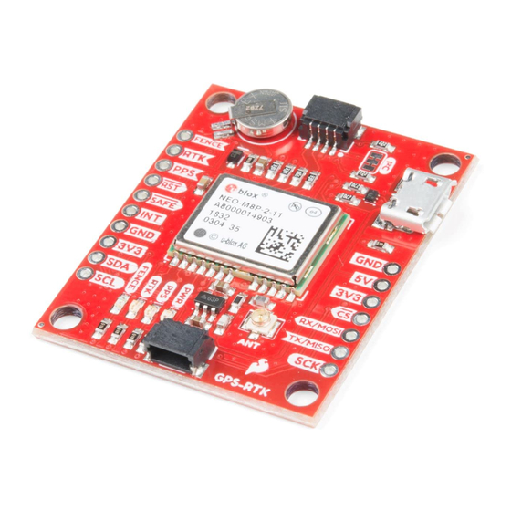
GPS-RTK Hookup Guide
Introduction
The NEO-M8P-2 module is the top-of-the-line module for high accuracy GNSS and GPS location solutions
including RTK. The NEO-M8P-2 is unique in that it is capable of both rover and base station operations. The '-2'
designation means this module has survey-in mode allowing the module to become a base station and produce
RTCM 3.x correction data. From here on we will refer to the module as NEO-M8P but it should not be confused
with the NEO-M8P-0 module (which is not able to produce RTCM data).
SparkFun GPS-RTK Board - NEO-M8P-2 (Qwiic)
GPS-15005
Product Showcase: SparkFun GPS-RTK Board
Advertisement

Subscribe to Our Youtube Channel
Related Manuals for sparkfun NEO-M8P-2


Summary of Contents for sparkfun NEO-M8P-2
- Page 1 The NEO-M8P-2 module is the top-of-the-line module for high accuracy GNSS and GPS location solutions including RTK. The NEO-M8P-2 is unique in that it is capable of both rover and base station operations. The ‘-2’ designation means this module has survey-in mode allowing the module to become a base station and produce RTCM 3.x correction data.
-
Page 2: Hardware Overview
Hardware Overview Communication Ports The NEO-M8P-2 in unique in that it has four communication ports which are all active simultaneously. You can read NMEA data over I2C while you send configuration commands over the UART and vice/versa. The only limit is that the SPI pins are mapped onto the I2C and UART pins so it’s either SPI or I2C+UART. - Page 3 The micro-B connector makes it easy to connect the NEO-M8P to u-center for configuration and quick viewing of NMEA sentences. It is also possible to connect a Raspberry Pi or other SBC over USB. The NEO-M8P enumerates as a serial COM port and it is a seperate serial port from the UART interface. See Getting Started with U-Center for more information about getting the USB port to be a serial COM port.
- Page 4 RTCM data into the module, etc. We’ve written a handful of sketches and an Arduino library to aid in using the NEO-M8P over I2C in a snap. You can get the library through the Arduino library manager by searching ‘SparkFun Ublox’. Checkout the GPS-RTK Arduino Library section for more information. UART/Serial The classic serial pins are available on the NEO-M8P but are shared with the SPI pins.
- Page 5 The NEO-M8P can also be configured for SPI communication. By default the SPI port is disable. To enable SPI close the DSEL jumper on the rear of the board. Closing this jumper will disable the UART and I2C interfaces. Control Pins The control pins are highlighted below.
- Page 6 These pins are used for various extra control of the NEO-M8P: FENCE: Geofence output pin. Configured with U-Center. Will go high or low when a geofence is setup. Useful for triggering alarms and actions when the module exits a programmed perimeter. RTK: RTK output pin.
- Page 7 LEDs The board includes four status LEDs as indicated in the image below. The power (PWR) LED will illuminate when 3.3V is activated either over USB or via the Qwiic bus. The pulse per second (PPS) LED will illuminate with each successful update once a position lock has been achieved.
-
Page 8: Connecting An Antenna
Jumpers There are four jumpers located on the back of the board to configure the GPS-RTK. Closing DSEL enables the SPI interface and disables the UART and I2C interfaces. USB will still function. Cutting the I2C jumper will remove the 2.2k Ohm jumpers from the I2C bus. If you have many devices on your I2C bus you may want to remove these jumpers. -
Page 9: Required Materials
This will provide a great stress relief for the antenna connection. Now attach your SMA antenna of choice. Be Careful! U.FL connectors are easily damaged. Make sure the connectors are aligned, flush face to face (not at an angle), then press down using a rigid blunt edge such as the edge of a PCB or point of a small flat head screwdriver. - Page 10 It’s ok if it is more than 10km (6 miles) away, we’re just practicing. Site P041 is pretty close to SparkFun HQ. We’ll be using it. To access UNAVCO data feeds you will need to send an email to rtgps@unavco.org to request credentials. Let UNAVCO know if you are affiliated with any business, school, or organization and if you are using the account for personal use.
- Page 11 From the input stream window click the check box next to ‘Base Station’, select NTRIP Client from the dropdown, and the RTCM 3 format. Next click on the small three dots under Opt - this will open the NTRIP client configuration options.
- Page 12 Once we have P041 located, we want the RTCM feed. Copy and paste that mountpoint back into RTKNAVI into the ‘Mountpoint’ box. Once you’ve entered all your credentials and mountpoint, click OK to close the NTRIP Client Options window. You can also close the Ntrip browser. The input stream should be configured so click OK in the Input Stream window to complete configuration.
- Page 13 Click the ‘…’ button to configure your serial port. Note that you’ll need to select the same baud rate as your GPS- RTK module is configured for. By default, the NEO-M8P communicates at 9600bps 8-N-1, so use this setting. Once you have things configured properly the TX LED on the Serial basic should blink once per second indicating the UNAVCO server is pushing data all the way down to the TX pin on the Serial Basic.
- Page 14 Bluetooth Mate Silver. It’s trivial to connect a Bluetooth serial device to the GPS-RTK serial pins. If you need maximum portability a radio link can be the lowest power, smallest footprint. SparkFun offers a variety of LoRa radios and antennas. With the help of a microcontroller these radios can pipe data from the LoRa backhaul over an Qwiic I2C port, serial, even SPI.
- Page 15 A standard camera tripod The NEO-M8P-2 can be configured using Serial, SPI, or I2C. We’re fans of the daisychain-ability of I2C so we’ll be focusing on the Qwiic system. For this exercise we’ll be connecting the an LCD and GPS-RTK to a BlackBoard...
- Page 16 Enable Survey-In mode for 5 minutes (300 seconds) Enable RTCM output messages Being Transmitting the RTCM packets over the backhaul of choice Be sure to grab the SparkFun Arduino Library for Ublox. You can easily install this via the library manager by searching ‘SparkFun Ublox’. Once installed click on File->Examples->SparkFun_Ublox_Arduino_Library...
- Page 17 If you have a ‘rover’ in the field in need of correction data you’ll need to get the RTCM bytes to the rover. The SparkFun Ublox library automatically detects the difference between NMEA sentences and RTCM data. The function allows you to ‘pipe’ just the RTCM correction data to the channel of your choice. Once the...
-
Page 18: Resources And Going Further
Have fun with your new found super power: sub decimeter grade GPS! For more on the GPS-RTK, check out the links below: Schematic (PDF) Example RTCM output from the NEO-M8P-2 NEO-M8P-2 Datasheet (PDF) Using U-Center to configure the NEO-M8P for base station RTCM output... - Page 19 What is GPS RTK? Documenting a six-month project to race autonomous Learn about the latest generation of GPS and GNSS Power Wheels at the SparkFun Autonomous Vehicle receivers to get 2.5cm positional accuracy! Competition (AVC) in 2016. Getting Started with U-Center Learn the tips and tricks to use the u-blox software tool to configure your GPS receiver.
Need help?
Do you have a question about the NEO-M8P-2 and is the answer not in the manual?
Questions and answers