Table of Contents
Advertisement
Quick Links
AST-CAN485 WiFi Shield Hookup Guide
Introduction
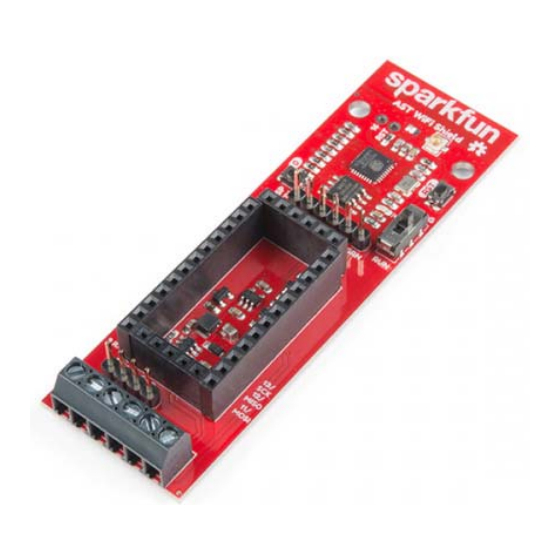
What would make the AST-CAN485 even better? WiFi! In order to further the communications
capabilities of the CAN485, we present the AST-CAN485 Wifi Shield. The shield is based on the
Sparkfun ESP8266 thing and allows for a CAN485 module to communicate over Wifi.
SparkFun AST-CAN485 WiFi Shield
WRL-14597
Page 1 of 16
...
Advertisement
Table of Contents

Related Manuals for sparkfun AST-CAN485


Summary of Contents for sparkfun AST-CAN485
- Page 1 What would make the AST-CAN485 even better? WiFi! In order to further the communications capabilities of the CAN485, we present the AST-CAN485 Wifi Shield. The shield is based on the Sparkfun ESP8266 thing and allows for a CAN485 module to communicate over Wifi.
-
Page 2: Required Materials
DEV-14483 Tools Depending on your setup, you will need a soldering iron, solder, and general soldering accessories to solder pins to the AST-CAN485. You will also need a flat head and wire strippers to connect wires to the screw terminals. -
Page 3: Suggested Reading
Pocket Screwdriver Set Wire Strippers - 20-30AWG TOL-12891 TOL-14763 Suggested Reading We recommend checking out the AST-CAN485 Hookup Guide to get started with the board. Depending on your setup, you may need to install custom libraries and board add-ons. - Page 4 If you aren’t familiar with the following concepts, we also recommend checking out these tutorials before continuing. Working with Wire ESP8266 Thing Development Board Hookup Guide How to strip, crimp, and work with wire. An overview of SparkFun's ESP8266 Thing Development Board - a development board for the Internet of Things.
-
Page 5: Hardware Overview
Hardware Overview Input Power The AST-CAN485 WiFi Shield provides screw terminals for your power, RS-485 signals, and CAN bus signals, presoldered to the board for fast and secure connections. The input voltage range is 7-24VDC. The input voltage is regulated down to 5V to supply power the... - Page 6 Page 6 of 16 ESP8266 Based on the SparkFun ESP8266 Thing, you can use either the PCB trace antenna, or the U.FL connector if housed in a metal enclosure.
-
Page 7: Programming Switch
Page 7 of 16 Programming Switch Because the UARTs are connected together for the CAN485 board and the ESP8266, a switch is used to separate the RX and TX signals. When programing either the ESP8266 or CAN485 board, move the switch over to the PROG position, and after the upload is complete, toggle the switch to the RUN position. - Page 8 Page 8 of 16 AST-CAN485 Serial Port A header breaks out the Software Serial port used by the CAN485. This can be used as a debugging serial port or to connect other devices.
- Page 9 Page 9 of 16 Pinouts The pinout for the WiFi Shield is shown below: Image courtesy of AST...
-
Page 10: Hardware Hookup
ESP8266 and communicate with the CAN485. The mode selection switch also enables the ESP to be programmed by disconnecting it from the CAN485. Hardware Hookup The AST-CAN485 WiFi Shield comes with headers pre-soldered to the board. Insert the CAN485 as shown with the CAN485's FTDI header close to the ESP8266. -
Page 11: Powering The Board
If this is your first time using Arduino, please review our tutorial on installing the Arduino IDE. If you have not previously installed an Arduino library or board add-on, please check out our library installation guide and instructions to install the AST-CAN485 board add-on files. The Programming Mode Selection Switch The ESP and CAN485 modules are connected using a hardware serial port. - Page 12 Page 12 of 16 Setup Arduino For ESP Programming There are many options for programming ESP8266 based devices. The approach recommended by this guide is to make use of the ESP8266 Arduino Addon which has been developed by the ESP community.
- Page 13 ESP8266 Thing Development Board Hookup Guide NOVEMBER 5, 2015 An overview of SparkFun's ESP8266 Thing Development Board - a development board for the Internet of Things. If you have not previously installed an Arduino library, please check out our installation guide.
- Page 14 ESP8266 in the ESP Arduino Library. These are accessible in the Arduino IDE under File>Examples. Examples may also be found in the ESP Github Community Forum. Resources and Going Further For more information, check out the resources below: AST-CAN485 WiFi Shield...
- Page 15 Page 15 of 16 • GitHub Product Repo • Schematic (PDF) • Eagle Files (ZIP) • SFE Product Showcase AST-CAN485 Dev Board • AST GitHub Repo ◦ CAN485 Product Repo ◦ AST CAN Library ◦ AST RS485 Library ◦ AST AltSoftSerial ◦...
- Page 16 Page 16 of 16 According to Pete: How RS-485 Works APRIL 2, 2018 https://learn.sparkfun.com/tutorials/ast-can485-wifi-shield-hookup-guide?_ga=2.175783717... 3/1/2019...
Need help?
Do you have a question about the AST-CAN485 and is the answer not in the manual?
Questions and answers