Advertisement
Quick Links
HARTING Electronics GmbH
P.O. Box 14 73 | D-32339 Espelkamp
HARTING.electronics@HARTING.com
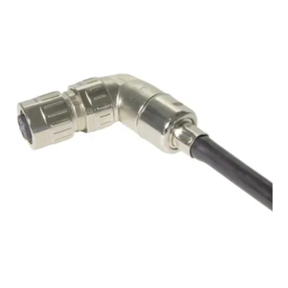
Rundsteckverbinder · Circular Connector · Connecteur circulaire
M12 male/female A-coded 5-pole
M12 male D-coded 4-pole
Bestell-Nummer · Part number · Réf. article
21 03 812 1511 + 21 03 812 2511 + 21 03 882 1411
www.HARTING.com
Inhalt · Content · Contenu
Bestell-Nummer
Part Number
21 03 812 1511 21 03 812 2511 21 03 882 1411
Réf. article
Kontaktträger
Contact holder
Support de contact
Steckverbinder-
gehäuse
Metal housing
Corps métallique
Wellenschlauch-
dichtung
Sealing cap
Joint d'étanchéité
Adapter
Adapter
Adaptateur
Dichtungskamm
Seal holder
Peigne de joints
Schirmring
Shielding ring
Tresse de blindage
Montagehilfe
Assembly aid
Dispositif de
montage
Oval-Sperre
Oval clip
Clip ovale
Montageanleitung
Deutsch
Assembly instruction · Instructions d'assemblage
English
Français
1. Wellenschlauch im Wellental gerade abschneiden.
1. Cut the conduit straight in the corrugation.
1. Couper la gaine annelé droite dans le creux de l'onde.
Hersteller
Manufacturer
Fabricant
PMA
2. Wellenschlauchdichtung ganz auf den Wellenschlauch aufschieben.
2. Push sealing cap completely onto conduit.
2. Pousser le joint d'étanchéité complètement sur la gaine.
3. Benötigte Dichtung ausbrechen.
3. Choose required seal.
3. Choisir le joint approprié.
4. Wellenschlauch mit der Wellenschlauchdichtung auf das Kabel schie-
ben. Adapter und Dichtung auf das Kabel schieben.
4. Push conduit with sealing cap over the cable. Push adapter and
seal onto the cable.
4. Pousser la gaine avec le joint d`étanchéité sur le câble. Pousser l'adap-
tateur et le joint sur le câble.
5. Kabelmantel entfernen. Schirmgeflecht umlegen. Evtl. Folien entfer-
nen. Anschließend Kabelenden abisolieren und Kontakte ancrimpen.
5. Remove outer cable jacket. Form shielding braid as shown. Remove
foils if necessary. Finally strip cable ends and crimp contacts.
5. Retirer le gainage. Rabattre la tresse de blindage. Enlever éventuelle-
ment le film de protection si nécessaire. Finalement dénuder les bouts
de câble et sertir les contacts.
Bezeichnung
Beschreibung
Designation
Description
Désignation
Description
Wellenschlauch
PCST-10B.50
Conduit
Gaine
7.2 - 8.8 mm
5.4 - 7.2 mm
4.5 - 5.4 mm
Bestell-Nummer
Part Number
21 03 812 1511 21 03 812 2511 21 03 882 1411
Réf. article
Abisolierlänge X
Stripping length X
21 – 23 mm
Longueur de dénudage X
6. Dichtung über Kabelmantel schieben, bis die Dichtung bündig mit der
Mantelisolation abschließt. Schirmgeflecht zur Dichtung umlegen.
6. Slide seal onto the cable and form shielding braid as shown.
Seal needs to be flush with the outer insulation.
6. Glisser le joint sur le câble jusqu'à ce que le joint soit aligné avec l'iso-
lant. Rabattre la tresse de blindage vers le joint.
7. Schirmring über Kabelenden auf Schirmgeflecht und Dichtung aufdrü-
cken. Dabei darauf achten, dass auf den Kodiernasen der Dichtung
kein Schirmgeflecht liegt. Überstehendes Schirmgeflecht abschnei-
den. Bei 4-poligem Anschluss weiter bei Punkt 9. Bei 5-poligem An-
schluss weiter bei Punkt 8.
7. Slide shielding ring over cable ends and assemble seal and
shielding ring. Make sure that no coding pin of the seal is
covered by shielding braid. Cut off shielding braid. If you have
a 4 pole wire please forward to point 9. If you have a 5 pole wire
please forward to point 8.
7. Glisser la bague de blindage sur les câbles et assembler le joint et la
bague. S'assurer qu'aucun pion de détrompage n'est couvert par la
tresse. Couper la tresse de blindage.
Pour une connexion 4 pôles, passer au point 9.
Pour une connexion 5 pôles, passer au point 8.
8. Mittleren Kontakt in den Kontaktträger einlegen. Kontaktträger zu-
sammendrücken und verrasten.
8. Insert the contact in the middle chamber of the contact holder.
Press the contact holder together.
8. Insérer le contact dans la cavité centrale du support de contact. Assem-
bler le support de contact.
X
4
19 – 21 mm
21 – 23 mm
Advertisement

Related Manuals for HARTING M12


Summary of Contents for HARTING M12
- Page 1 1. Wellenschlauch im Wellental gerade abschneiden. 1. Cut the conduit straight in the corrugation. Rundsteckverbinder · Circular Connector · Connecteur circulaire 1. Couper la gaine annelé droite dans le creux de l’onde. M12 male/female A-coded 5-pole M12 male D-coded 4-pole Bestell-Nummer Part Number 21 03 812 1511 21 03 812 2511 21 03 882 1411 Bestell-Nummer ·...
- Page 2 Si l’on courbe la gaine, veiller a respecter le rayon de courbure recom- 10. Assembler l’adaptateur. Retirer le dispositif de montage. Dynamometric screwdriver M12-L for SW17 mande. Le connecteur ne doit etre connecte ou deconnecte uniquement Tournevis dynamometrique M12-L pour SW17 09 99 000 0384 hors tension. Empfohlenes Crimpwerkzeug Recommended crimp tool...