Table of Contents
Advertisement
Quick Links
Installation Manual
Lithium Iron Phosphate Battery Modules
Kimbult Industrial Park, Unit C3 & C4
9 Zeiss Road
Laser Park, Honeydew
2040
South Africa
www.freedomwon.co.za
Technical and Installation Assistance – Contact:
Please contact your Freedom Won Distributor or Reseller Installer for technical and installation
support. A directory of Distributors and Reseller Installers is available at www.freedomwon.co.za.
For advanced support please contact support@freedomwon.co.za.
Update Record:
Revision
Update Summary
Number
0
First Release
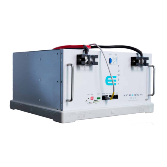
eTower
Manufactured By Freedom Won (Pty) Ltd
Updated By
Date of Issue
Antony English
01 October 2021
Advertisement
Table of Contents

Subscribe to Our Youtube Channel
Related Manuals for Freedom Won eTower


Summary of Contents for Freedom Won eTower
- Page 1 South Africa www.freedomwon.co.za Technical and Installation Assistance – Contact: Please contact your Freedom Won Distributor or Reseller Installer for technical and installation support. A directory of Distributors and Reseller Installers is available at www.freedomwon.co.za. For advanced support please contact support@freedomwon.co.za.
-
Page 2: Product Description
The eTower is designed primarily for systems that need to start with 5kWh initially with a view to growing the storage capacity over time in 5kWh increments up to 20kWh. - Page 3 Installation Manual Revision 0 8. Lite Industrial This manual covers only the eTower. Please refer to the manuals specific to the other ranges for help with those models. The eTower voltage is 52V nominal (to suit so called “48V” systems). This higher nominal voltage of 52V (compared to 48V nominal batteries) offers superior performance and efficiency owing to lower DC currents in the battery and in the inverter.
- Page 4 2.2.1 19” Rack Bracket Fixing Points The eTower modules can be installed into a standard 19” rack. There are three fixing threads on each side of the module near the front, as indicated, that match the 19” rack mount brackets available from Freedom Won on request. The primary installation arrangement is intended to be stacking the modules into a tower using the inter-module pedestal, but for applications requiring 19”...
- Page 5 Address Dip Switches Block The block with four binary dip switches must be set to a specific configuration that allocates the address of the eTower module. Each module must have its own address beginning with P a g e 4 | 23...
- Page 6 Note that is it important to set these dip switches correctly to ensure proper communication and system operation! Although the eTower communication protocol can accommodate up to 15 modules, the recommended limit is four modules per system because systems that require more than 20kWh are usually better accommodated by the Freedom Won LiTE range of high- performance batteries.
-
Page 7: Reset Button
Busbars must be staggered to alternate between left and right terminals when connecting towers of two or more modules. See Figure 2.3 showing a four-module eTower. The top module is fitted with two 35mm cables to accommodate the maximum power capability of the battery stack. - Page 8 Installation Manual Revision 0 Figure 2.3 Four-Module eTower P a g e 7 | 23...
-
Page 9: Circuit Breaker
There are two cable types with differing pin configurations included in each eTower package, one to suit Victron, and the other to suit what Freedom Won describes as Type 1 CAN Bus inverters. See the Freedom Won Inverter Interfacing Guide for complete details. -
Page 10: Detailed Specifications
DC chargers. The positive cable is red, and the negative cable is black. 2.2.19 Earthing Point For eTower modules installed into a cabinet this earth point may be used to ground all module casings to the cabinet ground. Detailed Specifications Table 2.1 provides an overview of important data pertaining to the eTower e5000 modules. - Page 11 Installation Manual Revision 0 P a g e 10 | 23...
- Page 12 Installation Manual Revision 0 P a g e 11 | 23...
- Page 13 DC terminals. The eTower modules are primarily designed to stand on the floor on the supplied pedestal but if space is a problem, they can also be placed on end against a wall with the front panel facing upwards.
- Page 14 3480. When shipped by sea the package must be labelled as such using the correct label (Fig 3.1). The eTower box has this label printed on it already, so this is only required if shipped inside another crate or packaging. The packaging design must also comply with the dangerous goods regulations, so should always be transported in its original packaging.
-
Page 15: Environmental Requirements
4.1.4 Mounting The first eTower module can be placed on the floor or a stand or shelf on its supplied pedestal, with units stacked on top of it, each sitting on their own pedestal, see Figure 2.3 for an example of a system stacked with four modules. The eTower must be placed on a firm level surface to ensure that the tower remains stable. - Page 16 10kVA, and two per pole for inverters up to 20kVA. The lugs for the eTower end of the DC cables are already fitted and the terminal bolts are long enough to accommodate both a busbar and a lug on the same terminal when required.
- Page 17 CAN it must first of all be equipped with a CAN interface as well as a suitable method of connecting the CAN wires. Further to this the eTower BMS must be programmed with a CAN messaging profile that is developed for the inverter or charge controller being used.
- Page 18 Installation Manual Revision 0 The CAN 2.0 Part A and Part B standard uses the SAE J1939 standard in the eTower. It is necessary to install a 120 Ohm resistor on each extreme end of the CAN cable (splices or branch connections do not require a resistor).
- Page 19 The Lite is fitted with an “ON/OFF” breaker. When this breaker is switched on the DC terminals of the eTower may immediately become live if the BMS is active. If the BMS is not active and the eTower detects an external voltage source the BMS will come alive, observed by the illumination of LED’s on the front panel.
- Page 20 BMS will be forced to intervene by internally disconnecting the cells from the terminals. The breaker will remain ON. Once the problem is cleared the eTower module may reconnect. Frequent occurrences of this situation is not desirable so the voltages should be set to the following to reduce this occurrence to abnormal circumstances: •...
- Page 21 Installation Manual Revision 0 10. Accessories Freedom Won includes the following accessories inside the eTower box as not additional charge: Table 9.1 List of Accessories Item Description 1 x Plastic pedestal For stacking multiple eTower modules on top of...
-
Page 22: Warranty And Repair
Installation Manual Revision 0 11. Warranty and Repair The eTower is sealed with a tamper proof warranty seal. It may not be opened by anyone other than Freedom Won and installers or repairers that have been explicitly approved by Freedom Won. - Page 23 I switch off the breaker hours of inactivity My battery will not charge at The eTower has an automatic charge limit feature where more than 20A the maximum charge current is reduced to 20A using the internal MOSFET controller if the charge current exceeds 85A for too long.
Need help?
Do you have a question about the eTower and is the answer not in the manual?
Questions and answers