Table of Contents
Advertisement
Quick Links
Advertisement
Table of Contents

Related Manuals for ratiotherm WP Max-Air


Summary of Contents for ratiotherm WP Max-Air
- Page 1 Technical Document WP Max-Air state 11/05/2020...
-
Page 2: Table Of Contents
CONTENTS 1. Functional description 2. Notes on the documentation 2.1 Fundamental safety instructions 2.2 Used symbols 2.3 Intended use 2.4 General safety instructions 2.5 Installation and adjustments 2.6 Guidlines, norms and laws 2.7 Qualification of personnel 2.8 Responsibility of personnel 3. -
Page 3: Functional Description
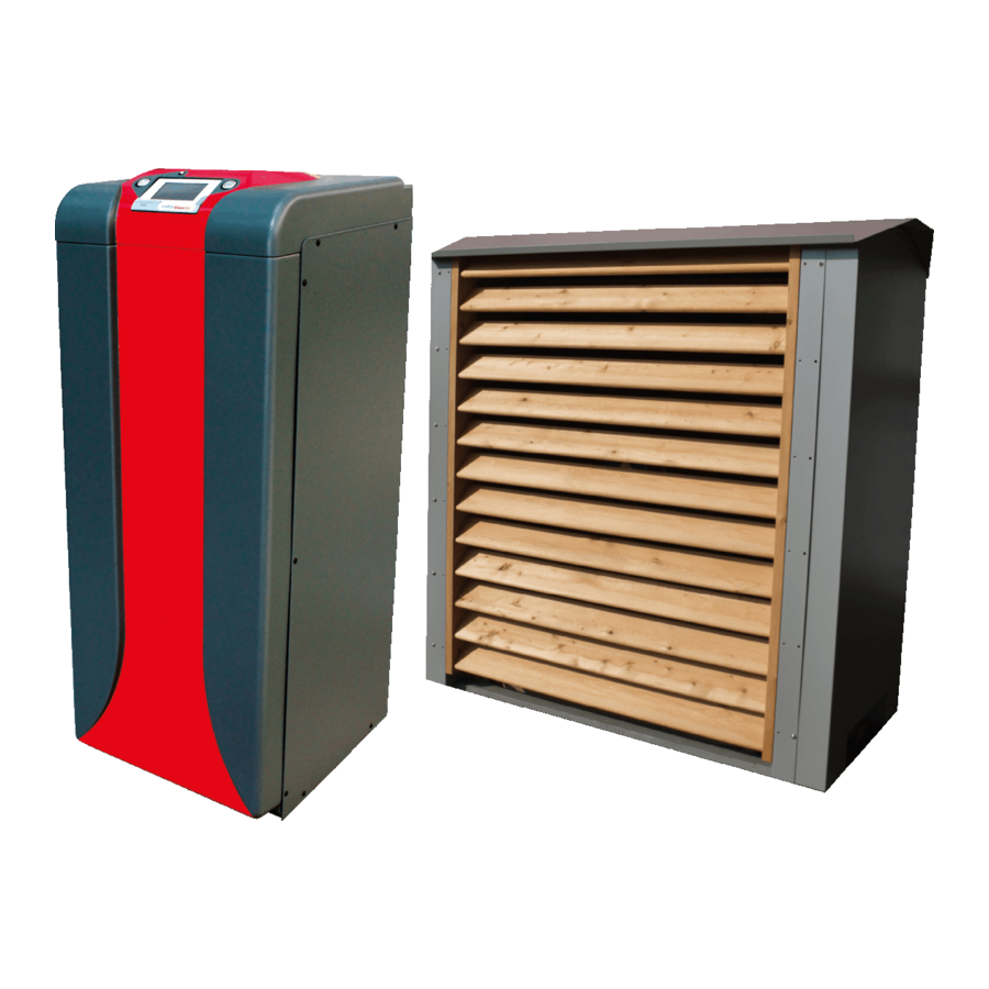
1. FUNCTIONAL DESCRIPTION The ratiotherm air heat pump WP Max-Air is designed as a split heat pump and guarantees a very quiet operation. The energy supply of the ambient air can be easily accessed by using the heat pump WP Max-Air. -
Page 4: Notes On The Documentation
Further documents besides this operating and installation instruction are valid. The operating and installation guide for technical staff is a part of the ratiotherm heat pump WP Max-Air. The ratiotherm heat pump WP Max-Air can not be used without this instruction. -
Page 5: Fundamental Safety Instructions
2. NOTES ON THE DOCUMENTATION 2.1 FUNDAMENTAL SAFETY INSTRUCTIONS DANGER! Imminent danger which causes grievous bodily harm or leads to death. Potentially dangerous situation, which could cause grievous bodily harm or lead to death. WARNING! Potentially dangerous situation, which could cause bodily harm. ATTENTION! Potentially dangerous situation, which could cause bodily harm or could damage components of the heat... -
Page 6: Used Symbols
2. NOTES ON THE DOCUMENTATION 2.2 USED SYMBOLS danger zone danger through electric current warning of hot surfaces and fluids STOP unlock before working note: damage read the instruction mandatory signs for wearing protective gear... -
Page 7: Intended Use
2. NOTES ON THE DODUMENTATION 2.3 INTENDED USE The ratiotherm heat pump WP Max-Air is constructed according to the state of the art and the certified safety regulations. The heat pump is only intended for the preparation of hot water and the generation of heat and cold in residential and / or non-residential buildings. -
Page 8: General Safety Instructions
Read and follow the instructions. • To avoid accidents and material damage observe the safety instructions. • Observe the national rules of the country in which the ratiotherm heat pump WP Max-Air is used. WARNING! DAMAGES POSSIBLE Do not make any changes: •... -
Page 9: Installation And Adjustments
2. NOTES ON THE DOCUMENTATION 2.5 INSTALLATION AND ADJUSTMENTS The installation, commissioning or dismantling of the device is only allowed to be done by technicians with specific knowledge. Applicable rules, requirements and guidelines as well as local installation specifications must be observed. ATTENTION! Safety valve and air outlet pipe During the heating process water volume increases. -
Page 10: Guidlines, Norms And Laws
2. NOTES ON THE DOCUMENTATION 2.6 GUIDLINES, NORMS AND LAWS When installing the heat pump, the following requirements, rules and guidelines have to be observed: IN GERMANY: • VDE- as well as EVU rules and requirements (especially VDE 0100); • Rules and requirements of the local utilities;... -
Page 11: Qualification Of Personnel
• the maintenance staff will adjust, test and repair the ratiotherm heat pump WP Max-Air in a way that no personal and material risks arise. TU_GB_WP_Max-Air_Flex12_2020/05-bi - Errors and changes of all information, pictures and drawings remain reserved. Compliance with the generally valid and recognized rules of technology must be strictly adhered to! -
Page 12: Responsibility Of Personnel
WP Max-Air; • the ratiotherm heat pump WP Max-Air is handed over and operated in a safe and working condition and that damages to the heat pump are removed immediatly or that the damaged heat pump gets shut down right away. -
Page 13: Technical Data
3. TECHNICAL DATA 3.1 TYPES, POWER, DIMENSIONS, WEIGHT Max-Air (air/water) power data heat mode A+2/W35 heat output 3.6 to 17 .7 power consumption 0.8 to 3.4 coefficient of performance 5.11 power data cooling mode W15/A35 cooling capacity 4.3 to 21.4 power consumption 1.0 to 4.1 coefficient of performance... - Page 14 3. TECHNICAL DATA 3.1 TYPES, POWER, DIMENSIONS, WEIGHT Max-Air (air/water) device data sound pressure level inner part dB (A) at a distance of 1 m sound pressure level outdoor unit dB (A) at a distance of 1 m dimensions inner part 500 x 1300 x 540 wxhxd (mm) dimensions outdoor unit...
-
Page 15: Performance Curve
3. TECHNICAL DATA 3.2 PERFORMANCE CURVE Coefficient of performance, heat output and power consumption at varying speeds: Coefficient of performance Coefficient of performance at 100 % Coefficient of performance at 75 % Coefficient of performance at 50 % Coefficient of performance at 25 % Heat output Heat output in kW at 100 % Heat output in kW at 75 %... -
Page 16: Mechanical Installation
A floor drain must be provided as protection against water damage. • The ratiotherm heat pump WP Max-Air has to be installed at a clean, ventilated and dry location. The ambient temperature must be > 10 °C and < 35 °C year round. -
Page 17: External Unit
5 meters lower or 9 meters higher than the indoor unit • If larger height differences are required, please ask ratiotherm. • The outdoor unit can be set up in max. 20 m distance (simple cable length) from the indoor unit, longer cable lengths are only possible after consultation with ratiotherm. -
Page 18: Foundation Plan
4. MECHANICAL INSTALLATION 4.2 EXTERNAL UNIT top view: air ejection direction 4.3 FOUNDATION PLAN infiltration area (e.g. gravel) view below: draining area... -
Page 19: Add-On Module Hybrid
20.04.2020 Habermeyer Projekt: Bezeichnung: Geprüft: Hybrid-Zusatzmodul Ab- und für WP Max-Air Anschlussmaße Genehmigt: ratiotherm Heizung + Solartechnik GmbH & Co. KG D- 91795 Wellheimer Str. 34 Tel. +49 (0)8422 / 9977 - 0 Fax. +49 (0)8422 / 9977 - 30 info@ratiotherm.de | www.ratiotherm.de... -
Page 20: Hydraulic Installation
5. HYDRAULIC INSTALLATION 5.1 CONNECTION SIZES AND DIMENSION suction gas connection 18 mm liquid connection 12 mm heating flow 1 1/4“ AG heating return 1 1/4“ AG additional source entry 1“ AG (option hybrid effect) additional source exit 1“ AG (option hybrid effect) •... -
Page 21: Scheme: Standard Without Solar
5. HYDRAULIC INSTALLATION 5.2 SCHEME: STANDARD WITHOUT SOLAR TU_GB_WP_Max-Air_Flex12_2020/05-bi - Errors and changes of all information, pictures and drawings remain reserved. Compliance with the generally valid and recognized rules of technology must be strictly adhered to! ATTENTION! Installation and wiring only by authorized specialists. -
Page 22: Scheme: Standard With Solar
5. HYDRAULIC INSTALLATION 5.3 SCHEME: STANDARD WITH SOLAR... -
Page 23: Scheme: Full Scheme With Hybrid And Cooling
5. HYDRAULIC INSTALLATION 5.4 SCHEME: FULL SCHEME WITH HYBRID AND COOLING TU_GB_WP_Max-Air_Flex12_2020/05-bi - Errors and changes of all information, pictures and drawings remain reserved. Compliance with the generally valid and recognized rules of technology must be strictly adhered to! ATTENTION! Installation and wiring only by authorized specialists. -
Page 24: Pressure Loss Diagram
5. HYDRAULIC INSTALLATION 5.5 PRESSURE LOSS DIAGRAM... -
Page 25: Pressure Loss Diagram Hybrid
5. HYDRAULIC INSTALLATION 5.6 PRESSURE LOSS DIAGRAM HYBRID TU_GB_WP_Max-Air_Flex12_2020/05-bi - Errors and changes of all information, pictures and drawings remain reserved. Compliance with the generally valid and recognized rules of technology must be strictly adhered to! ATTENTION! Installation and wiring only by authorized specialists. -
Page 26: Requirements For The Quality Of The Heating Water
5. HYDRAULIC INSTALLATION 5.7 REQUIREMENTS FOR THE QUALITY OF THE HEATING WATER A maximum of 50 % glycol may be present in the system water. Parameter Unit Concentration Copper brazed < 6.0 6.0 - 7 .5 ° pH level 7 .5 - 8.5 8.5 - 10.0 °... -
Page 27: Electrical Installation
6. ELECTRICAL INSTALLATION 6.1 NOTES • The power supply of the heater is controlled by the control cabinet and it has to be protected by a fault-current circuit breaker with a trip current of not more than 30 mA (RCD) and with the fitting power. •... -
Page 28: Terminal Diagram And Description
CAN-Connection to Internal Unit Unit • X3.1, X3.4 and X3.6 are not necessary when using the ratiotherm rZR 16x2 as the main controller! However parallel use for Power-to-Heat is possible. • X3.2 and X3.3 are used to process a signal from the network operator/energy supplier. X3.2 is downward compatible with the utility contact. -
Page 29: Can-Bus Plan
6. ELECTRICAL INSTALLATION 6.4 CAN-BUS PLAN WALL CONTROLLER TERM MAIN CONTROLLER 16x2 OPEN OPTION HEATING ROD CAN-L CAN-H 12 V Pay attention to the correct wiring OPEN of the CAN-Bus! No star-shaped gird! HEAT PUMP Use a shielded, 4-pole cable! Pay attention to the instructions of the technische Alternative! OPEN... -
Page 30: Refrigeration Installation
7 . REFRIGERATION INSTALLATION 7 .1 PIPE DIMENSIONING ACCORDING TO DISTANCE TO EXTERNAL PART The values given are guidelines. In the case of widely branched pipelines, different cooling capacities, risers and partial-load operation, an exact pipeline calculation is necessary. The specified tube outer dimensions were calculated using commercially available software. - Page 31 7 . REFRIGERATION INSTALLATION 7 .1 PIPE DIMENSIONING ACCORDING TO DISTANCE TO EXTERNAL PART Pressure drop Pressure and suction line 1 - 2 K This corresponds to 0.1 - 0.5 bar, depending on the evaporation temperature t and refrigerant. Condensate line The maximum flow velocity should be w = 0.5 m/s.
-
Page 32: Cooling Scheme
7 . REFRIGERATION INSTALLATION 7 .2 COOLING SCHEME... -
Page 33: Structure And Function
8.1 ASSEMBLY AND SPARE PARTS The ratiotherm air heat pump WP Max-Air has a complete cooling circuit and uses the outside air as a primary energy source. The air heat pump is designed for all weather conditions. The outdoor part is installed in such a way that air can flow unhindered through the evaporator and does not recirculate. - Page 34 8. STRUCTURE AND FUNCTION 8.1 ASSEMBLY AND SPARE PARTS 4-way-valve Pressure transmitter ra/11360 + ra/10993 high pressure ra/13049 Pressure transmitter Sight glass ra/13049 ra/13055 Inverter High pressure ra/13024 safety limiter ra/13054 2x Immersion sensor ra/11997 Compressor ra/13026 3x Contact sensor ra/12007 4x Adjustable foot ra/13176...
- Page 35 8. STRUCTURE AND FUNCTION 8.1 ASSEMBLY AND SPARE PARTS Expansion valve ra/13036 ra/13411 Temperature sensor Temperature sensor ra/12007 ra/11998 Electrical box Contact sensor for ra/12603 expansion valve ra/13440 Heat exchanger ra/10339 Temperature sensor ra/13445 Check valve ra/10528 Pressure transmitter ra/13048 Evaporator ra/13446 Controller...
-
Page 36: Noise Exposure Of The External Unit
8. STRUCTURE AND FUNCTION 8.2 NOISE EXPOSURE OF THE EXTERNAL UNIT Power 30 % 100 % 30.4 dB 31.8 dB 30.4 dB 33.1 dB 30.5 dB 38.0 dB Power 30 % 100 % Power 30 % 100 % 30.5 dB 30.8 dB 30.5 dB 30.8 dB 30.5 dB 31.0 dB... -
Page 37: Control Logic
Control logic in conjunction with external controllers: • The request via external controller has priority over ratiotherm controllers (keyword: Power-to- Heat). • The heat pump can be requested via digital signal. -
Page 38: Hybrid Option
8. STRUCTURE AND FUNCTION 8.4 HYBRID OPTION Optionally, a second evaporator can be installed when ordering. Retrofitting is not possible! The 2nd evaporator is a smaller plate heat exchanger. This allows a wide range of hydraulic options: • Integration of a further brine- or water-based source such as: •... -
Page 39: Operating Instructions
9. OPERATING INSTRUCTIONS 9.1 CONTROLLER OPERATION • The rZR16x2 is operated by a 4,3“ Touch-Screen. • For an easier handling a touch pen is attached below the controller. • With the touch pen you can operate the surface and scroll by moving the scroll bar. •... - Page 40 9. OPERATING INSTRUCTIONS 9.1 CONTROLLER OPERATION Overview of the menu structure:...
- Page 41 9. OPERATING INSTRUCTIONS 9.1 CONTROLLER OPERATION Heating rod activ for 24 hours: ON Clearance: ON The heating rod can be switched on Heat pump is allowed to start upon request. regardless of the bivalence temperature. Enter password Enter the expert password to get to the expert menu.
- Page 42 9. OPERATING INSTRUCTIONS 9.1 CONTROLLER OPERATION K11 S4 temperature - compressor exit K12 S1 temperature - air out + fan K11 S5 temperature - compressor entry malfunction K11 S6 temperature - heat pump flow K12 S3 temperature evaporator K11 S7 high pressure K12 S4 low pressure...
- Page 43 9. OPERATING INSTRUCTIONS 9.1 CONTROLLER OPERATION Minor menu To get to the minor menu you have to press the display for 5 seconds. In the minor menu you are able to change the basic settings and get to the controller menu. Controller menu Link to the controller menu.
-
Page 44: Settings/Fixed Values
9. OPERATING INSTRUCTIONS 9.2 SETTINGS/FIXED VALUES Fixed values Description Setting Default possibilities User Bivalence temperature Outdoor temperature threshold at which the -30 °C to -7 °C 2nd energy generator (heating rod) is enabled. 15 °C rpm compr. DHW Target speed for hot water demand 0 % to 100 % 70 % rpm compr. - Page 45 9. OPERATING INSTRUCTIONS 9.2 SETTINGS/FIXED VALUES Fixed values Description Attitudinal Default possibilities Frost protection Minimum temperature at which an frost malfunction protection error or a frost protection 0 °C to 15 °C 8 °C malfunction is triggered. Time LP/HP error Time blockade for restart if LP/HP error 0 to 24 h 5 min...
- Page 46 9. OPERATING INSTRUCTIONS 9.2 SETTINGS/FIXED VALUES Fixed values Description Attitudinal Default possibilities Blockade time Time block for restart when system is switched 0 to 20 min 5 min off/on. Minimum running time Minimum running time of the heat pump 0 to 20 min 5 min Hybrid option Start opening ex-valve...
-
Page 47: Debugging
10. DEBUGGING HIGH PRESSURE Error message HP error HP disruption Error description High pressure protection of the refrigeration circuit is triggered. Behaviour of the heat • Heat pump is locked for 5 min. • Heat pump is locked. pump • If there are 3 errors in one hour, the •... - Page 48 10. DEBUGGING INVERTER Error message Inverter disruption Error description Malfunction contact of the inverter does not lock. Behaviour of the heat • Heat pump is locked. pump • Unlocking of the heat pump by using the reset-button. Error reason • Missing power supply •...
-
Page 49: Service & Maintenance
Prerequisite for a lengthy operational readiness, operational safety and for a high reliability are maintenances of the device on a regular basis by an accepted, qualified and by ratiotherm authorised technician. We suggest to execute the maintenance once a year. -
Page 50: Tightness Check
Risk of material and personnel damages due to improper handling! • Never try to do maintenance or repair work at the heat pump yourself. • For maintenance or repair work commission an accepted, qualified and by ratiotherm authorised technician. • We suggest the conclusion of a maintenance agreement. -
Page 51: Decommissioning & Disposal
12. DECOMMISSIONING & DISPOSAL When terminating the operation of the heat pump, the dismantling of the machine can only be done by qualified personnel. It should be ensured, that hazardous substances and waste are disposed of properly. Beachten Sie bei Demontage der Wärmepumpe die Hinweise zu Beginn der Technischen Unterlage sowie die unten aufgeführten Sicherheitshinweise. -
Page 52: Appendix
13. APPENDIX 13.1 ELECTRICAL PLAN... - Page 53 13. APPENDIX 13.1 ELECTRICAL PLAN TU_GB_WP_Max-Air_Flex12_2020/05-bi - Errors and changes of all information, pictures and drawings remain reserved. Compliance with the generally valid and recognized rules of technology must be strictly adhered to! ATTENTION! Installation and wiring only by authorized specialists.
- Page 54 13. APPENDIX 13.1 ELECTRICAL PLAN ...
- Page 55 13. APPENDIX 13.1 ELECTRICAL PLAN TU_GB_WP_Max-Air_Flex12_2020/05-bi - Errors and changes of all information, pictures and drawings remain reserved. Compliance with the generally valid and recognized rules of technology must be strictly adhered to! ATTENTION! Installation and wiring only by authorized specialists.
- Page 56 13. APPENDIX 13.1 ELECTRICAL PLAN ...
-
Page 57: Pump Wilo-Para Stg
13. ANNEX 13.2 PUMP WILO-PARA STG Technical data Connection voltage 1 ~ 230 V +10 %/-15 %, 50/60 Hz Protection class IP X4D Energy efficiency index EEI See rating plate (6) Fluid temperatures at max. ambient -20 °C to +95 °C (Heating/GT) temperature -10 °C to +110 °C (ST) Ambient temperature... - Page 58 13. ANNEX 13.2 PUMP WILO-PARA STG CONTROL MODES AND FUNCTIONS Constant differential pressure Δp-c (I, II, III) Recommended for underfloor heating or for large-sized pipes, applications without a variable pipe network curve (e.g. storage charge pumps) or single-pipe heating systems with radiators. The control keeps the set delivery head constant irrespective of the pumped volume flow.
- Page 59 13. ANNEX 13.2 PUMP WILO-PARA STG iPWM 1 mode (heating application): In iPWM 1 mode, the pump speed is controlled according to the PWM input signal. Behaviour in the event of a cable break: If the signal cable is separated from the pump, e.g. due to a cable break, the pump accelerates to maximum speed.
- Page 60 13. ANNEX 13.2 PUMP WILO-PARA STG Venting The pump venting function is activated by pressing and holding the operating button (for 3 seconds) and automatically vents the pump. The heating system is not vented. Manual restart A manual restart is initiated by pressing and holding the operating button (for 5 second) and unblocks the pump if required (e.g.
-
Page 61: Error Messages Frequency Inverter Bonfiglioli Agile
13. ANNEX 13.3 ERROR MESSAGES FREQUENCY INVERTER BONFIGLIOLI AGILE TU_GB_WP_Max-Air_Flex12_2020/05-bi - Errors and changes of all information, pictures and drawings remain reserved. Compliance with the generally valid and recognized rules of technology must be strictly adhered to! ATTENTION! Installation and wiring only by authorized specialists. - Page 62 13. ANNEX 13.3 ERROR MESSAGES FREQUENCY INVERTER BONFIGLIOLI AGILE...
- Page 63 13. ANNEX 13.3 ERROR MESSAGES FREQUENCY INVERTER BONFIGLIOLI AGILE TU_GB_WP_Max-Air_Flex12_2020/05-bi - Errors and changes of all information, pictures and drawings remain reserved. Compliance with the generally valid and recognized rules of technology must be strictly adhered to! ATTENTION! Installation and wiring only by authorized specialists.
-
Page 64: Technical Data Uvr 16X2
13. APPENDIX 13.4 TECHNICAL DATA UVR 16X2 UVR16x2-E terminal diagram Outputs 3/4, 8/9, 10/11 for mixer connection potential-free... - Page 65 13. APPENDIX 13.4 TECHNICAL DATA UVR 16X2 Technical data UVR16x2 (Relay versions) All inputs sensors RAS or RASPT, radiation sensor GBS01, thermocouple THEL, humidity sensor RFS, rain sensor RES01, pulses max. 10 Hz (e.g. for flow rate transducer VSG), voltage up to 3.3 V DC, resistance (1-100 Input 7 Also voltage 0-10 V DC Input 8...
-
Page 66: Refrigerant R410A
13. APPENDIX 13.5 REFRIGERANT R410A... - Page 67 13. APPENDIX 13.5 REFRIGERANT R410A TU_GB_WP_Max-Air_Flex12_2020/05-bi - Errors and changes of all information, pictures and drawings remain reserved. Compliance with the generally valid and recognized rules of technology must be strictly adhered to! ATTENTION! Installation and wiring only by authorized specialists.
- Page 68 13. APPENDIX 13.5 REFRIGERANT R410A...
- Page 69 13. APPENDIX 13.5 REFRIGERANT R410A TU_GB_WP_Max-Air_Flex12_2020/05-bi - Errors and changes of all information, pictures and drawings remain reserved. Compliance with the generally valid and recognized rules of technology must be strictly adhered to! ATTENTION! Installation and wiring only by authorized specialists.
-
Page 70: Compressor Oil
13. APPENDIX 13.6 COMPRESSOR OIL... - Page 71 13. APPENDIX 13.6 COMPRESSOR OIL TU_GB_WP_Max-Air_Flex12_2020/05-bi - Errors and changes of all information, pictures and drawings remain reserved. Compliance with the generally valid and recognized rules of technology must be strictly adhered to! ATTENTION! Installation and wiring only by authorized specialists.
- Page 72 13. APPENDIX 13.6 COMPRESSOR OIL...
- Page 73 13. APPENDIX 13.6 COMPRESSOR OIL TU_GB_WP_Max-Air_Flex12_2020/05-bi - Errors and changes of all information, pictures and drawings remain reserved. Compliance with the generally valid and recognized rules of technology must be strictly adhered to! ATTENTION! Installation and wiring only by authorized specialists.
-
Page 74: Label
13. APPENDIX 13.7 LABEL I ra�otherm II WP Max-Air 35 °C 11,1 13,3 14,5 2019 811/2013... -
Page 75: Ec Declaration Of Conformity
13.8 EC DECLARATION OF CONFORMITY EC declaration of conformity within the meaning of the EC Machinery Directive 2006/42/EC, Annex II, Part 1. A, EU-OJ L 157/24, 09/06/2006 ratiotherm GmbH & Co. KG Manufacturer and address: Wellheimer Straße 34 91795 Dollnstein... - Page 76 You can find us here ratiotherm GmbH & Co. KG Wellheimer Straße 34 91795 Dollnstein Direct contact: T +49 (0) 8422.9977-0 info@ratiotherm.de www.ratiotherm.de...
Need help?
Do you have a question about the WP Max-Air and is the answer not in the manual?
Questions and answers