Table of Contents
Advertisement
Quick Links
Advertisement
Table of Contents

Related Manuals for ratiotherm WP Max-Air


Summary of Contents for ratiotherm WP Max-Air
- Page 1 Technical Document WP Max-Air State 07.06.2019...
-
Page 2: Table Of Contents
TABLE OF CONTENTS 1. Functional description 2. Notes on the documentation 2.1 Basic safety instructions 2.2 Symbols used 2.3 Intended Use 2.4 General safety instructions 2.5 Installation and adjustment 2.6 Directives, standards and laws 2.7 Qualification of personnel 2.8 Responsibility of the skilled technician 3. -
Page 3: Functional Description
Integrated energy management (SG capable) • Very quiet outdoors • With ratiotherm components, a completely compatible, future-proof system TU_EN_WP_Max-Air_Flex_12_2019.09-Errors and changes of all data, pictures and drawings are reserved. Compliance with the generally applicable and recognised rules of technology is imperative! -
Page 4: Notes On The Documentation
The instructions must be made available to the operator and the specialist tradesman at all times for information purposes. If the ratiotherm WP Max-Air air heat pump is sold, the instructions must be supplied with it. We accept no liability for damage caused by non-compliance with these instructions. -
Page 5: Basic Safety Instructions
2. NOTES ON THE DOCUMENTATION 2.1 BASIC SAFETY INSTRUCTIONS DANGER! Immediate threat of danger, which could result in serious injury or death. Possibly dangerous situation, that could result in serious injury or death. WARNING! Possibly dangerous situation, that could lead to assault. BEWARE! Possibly dangerous situation, that could result in personal injury or damage to a component or thing in... -
Page 6: Symbols Used
2. NOTES ON THE DOCUMENTATION 2.2 SYMBOLS USED danger spot danger from electric current Warning of hot surfaces STOP and liquids activate before working advice against damage read operating instructions... -
Page 7: Intended Use
2. NOTES ON THE DOCUMENTATION 2.3 INTENDED USE The ratiotherm WP Max-Air air heat pump has been built in accordance with the state of the art and recognised safety regulations. The heater is intended exclusively for domestic and / or commercial use for hot water preparation (domes- tic hot water) and for heating or cooling. -
Page 8: General Safety Instructions
In order to avoid accidents and damage to property, the safety instructions must be observed! • The national regulations of the country in which the ratiotherm WP Max-Air air heat pump is used must be observed. WARNING! DAMAGE POSSIBLE Do not make any changes: •... -
Page 9: Installation And Adjustment
2. NOTES ON THE DOCUMENTATION 2.5 INSTALLATION AND ADJUSTMENT The installation, commissioning or dismantling of the device may only be carried out by a specialist with specific knowledge which is necessary for the activities with this device. The existing regulations, rules and guidelines as well as the local installation specifications must be observed. -
Page 10: Directives, Standards And Laws
2. NOTES ON THE DOCUMENTATION 2.6 DIRECTIVES, STANDARDS AND LAWS When setting up and installing the heater, the following regulations, rules and guidelines must be observed: IN GERMANY: • VDE and EVU regulations and provisions (in particular VDE 0100); • Regulations and rules of local utilities;... -
Page 11: Qualification Of Personnel
By personnel we mean all persons who work on the ratiotherm WP Max-Air air heat pump. In this sense, trainees are not qualified personnel. -
Page 12: Responsibility Of The Skilled Technician
• the personnel is instructed by the responsible superior and unauthorised persons are kept away from the ratiotherm WP Max-Air air heat pump; • the ratiotherm WP Max-Air air heat pump is only handed over and operated in a safe and functional condition and any damage to the heat pump is repaired immediately or the damaged heat pump is shut down immediately. -
Page 13: Technical Data
3. TECHNICAL DATA 3.1 TYPES, POWER, DIMENSIONS, WEIGHT MaxAir (Air/Water) Flex 12 Performance data heating mode A+2/W35 rated speed=5400U/min (1800 to 7200 rpm) Heating capacity 13,3 (3,6 to 17 ,7) Power consumption 2,6 (0,8 to 3,4) Coefficient of performance 5,11 W15/A35 rated speed=5400U/min (1800 to 7200 rpm) Cooling capacity... - Page 14 3. TECHNICAL DATA 3.1 TYPES, POWER, DIMENSIONS, WEIGHT Electrics Mains connection 400 V / 3~ / 50 Hz Slow fuse max. operating current compressor Instrument data Sound pressure level interal unit dB (A) at 1m distance Sound pressure level external unit dB (A) at 1m distance Measurements internal unit...
-
Page 15: Mechanical Installation
4.1 INTERNAL UNIT Installation conditions: • The ratiotherm WP Max-Air air heat pump must be installed in a clean, ventilated and dry place. The ambient temperature must be >10°C permanently. • The minimum distances must be observed for maintenance reasons. -
Page 16: External Unit
Outdoor unit max. 5 metres lower or 9 metres higher than indoor unit • If larger differences in height are required, please contact ratiotherm if necessary. • The outdoor unit can be installed as standard at a distance of max. 20 m (single cable length) from the indoor unit, longer cable lengths are only possible after consultation with ratiotherm. -
Page 17: Foundation Plan
4. MECHANICAL INSTALLATION 4.2 EXTERNAL UNIT top view: air ejection direction 4.3 FOUNDATION PLAN seepage area (e.g. gravel) bottom view: drip-off area TU_EN_WP_Max-Air_Flex_12_2019.09-Errors and changes of all data, pictures and drawings are reserved. Compliance with the generally applicable and recognised rules of technology is imperative! ATTENTION! Installation, wiring only by authorised specialist personnel. -
Page 18: Hydraulic Installation
5. HYDRAULIC INSTALLATION 5.1 CONNECTION MEASUREMENTS AND DIMENSIONS • Shut-offs and vents must be provided on site. • A vibration decoupled connection via hoses is recommended. Recommendation: Cornerstone TWS 32 • Please fill the system via the return line. • A drain tap is installed in the system on the heating side. -
Page 19: Scheme: Standard Without Solar (Connection Hc Rt At 4)
5. HYDRAULIC INSTALLATION 5.2 SCHEME: STANDARD WITHOUT SOLAR (CONNECTION HC RT AT 4) TU_EN_WP_Max-Air_Flex_12_2019.09-Errors and changes of all data, pictures and drawings are reserved. Compliance with the generally applicable and recognised rules of technology is imperative! ATTENTION! Installation, wiring only by authorised specialist personnel. -
Page 20: Scheme: Standard With Solar (Connection Hc Rt At 6)
5. HYDRAULIC INSTALLATION 5.3 SCHEME: STANDARD WITH SOLAR (CONNECTION HC RT AT 6) -
Page 21: Scheme: Full Scheme With Hybrid And Cooling
5. HYDRAULIC INSTALLATION 5.4 SCHEME: FULL SCHEME WITH HYBRID AND COOLING TU_EN_WP_Max-Air_Flex_12_2019.09-Errors and changes of all data, pictures and drawings are reserved. Compliance with the generally applicable and recognised rules of technology is imperative! ATTENTION! Installation, wiring only by authorised specialist personnel. -
Page 22: Pressure Loss Chart
5. HYDRAULIC INSTALLATION 5.5 PRESSURE LOSS CHART... -
Page 23: Pressure Loss Chart Hybrid
5. HYDRAULIC INSTALLATION 5.6 PRESSURE LOSS CHART HYBRID TU_EN_WP_Max-Air_Flex_12_2019.09-Errors and changes of all data, pictures and drawings are reserved. Compliance with the generally applicable and recognised rules of technology is imperative! ATTENTION! Installation, wiring only by authorised specialist personnel. -
Page 24: Requirements For Heating Water
5. HYDRAULIC INSTALLATION 5.7 REQUIREMENTS FOR HEATING WATER Parameter Unit Concentration Copper brazed < 6,0 6,0 - 7 ,5 ° pH level 7 ,5 - 8,5 8,5 - 10,0 ° > 10 ° < 10 10 - 500 Conductivity µS/cm 500 - 1.000 °... -
Page 25: Electrical Installation
6. ELECTRICAL INSTALLATION 6.1 CLUES • The power supply to the heater must come from the control panel and must be protected by a residual current circuit breaker with a tripping current not exceeding 30mA (RCD) of appropriate rating. • The RCD must be marked separately for the heater, e.g. -
Page 26: Terminal Diagram And Description
CAN-connection to internal unit unit • X3.1, X3.4 and X3.6 are not necessary when using the ratiotherm rZR 16x2 as main controller! Parallel use for Power-to-Heat however possible. • X3.2 and X3.3 are used to process a signal from the network operator/power supplier. X3.2 is downward compatible to the EVU contact. -
Page 27: Can-Bus Plan
6. ELECTRICAL INSTALLATION 6.4 CAN-BUS PLAN WALL CONTROLLER TERM MAIN CONTROLLER 16x2 OPEN OPTION HEATING ROD CAN-L CAN-H 12 V Ensure correct wiring of the CAN OPEN bus! No star-shaped network! HEAT PUMP Use shielded, 4-pin cable! Follow the instructions of the technical alternative. -
Page 28: Refrigeration Installation
7 . REFRIGERATION INSTALLATION 7 .1 PIPE SIZING ACCORDING TO DISTANCE TO EXTERNAL UNIT The values given are guide values. In the case of widely branched pipelines, other cooling capacities, risers and partial load operation, a precise pipeline calculation is necessary. The specified external pipe dimensions were calculated using standard software. - Page 29 7 . REFRIGERATION INSTALLATION 7 .1 PIPE SIZING ACCORDING TO DISTANCE TO EXTERNALUNIT Drop in pressure Pressure and suction line 1 - 2 K Depending on the evaporation temperature, this corresponds to t and refrigerant 0,1 - 0,5 bar. Condensate line The maximum flow velocity should be w = 0.5 m/s.
-
Page 30: Cooling Pattern
7 . REFRIGERATION INSTALLATION 7 .2 COOLING SCHEME... -
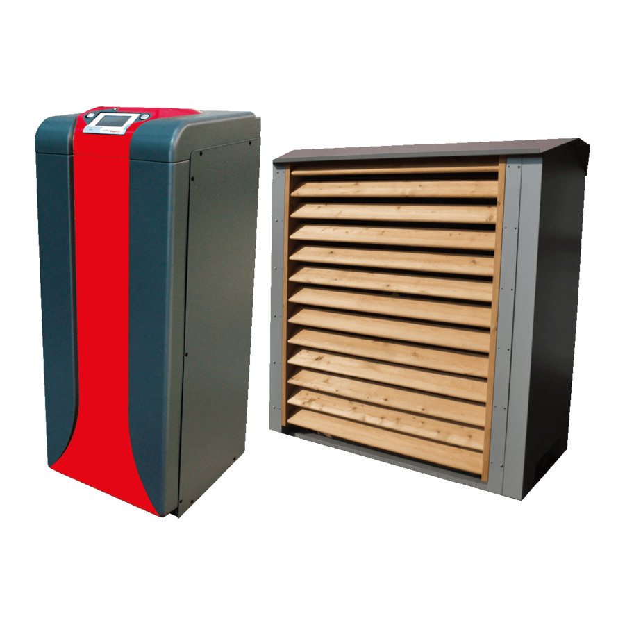
Page 31: Structure And Function
8.1 STRUCTURE AND SPARE PARTS The ratiotherm WP Max-Air air heat pump has a complete refrigeration circuit and uses the outside air as its primary energy source. The air heat pump is designed for all weather conditions. The outdoor part is installed outdoors in such a way that air can flow freely through the evaporator and is not recirculated. - Page 32 8. STRUCTURE AND FUNCTION 8.1 STRUCTURE AND SPARE PARTS pressure transmitter pressure transmitter low pressure high pressure ra/13048 ra/13049 4-way valve inspection glass ra/11360 + ra/10993 ra/13055 inverter high-pressure ra/13288 safety limiter ra/13054 solenoid valve ra/12731 + ra/12149 compressor ra/13026 2x immersion sensor ra/11997 4x contact sensor...
- Page 33 8. STRUCTURE AND FUNCTION 8.1 STRUCTURE AND SPARE PARTS Ex-valve ventilator ra/13036 ra/13411 temperature sensor temperature sensor ra/12007 ra/11998 electrical box contact sensor for ra/12603 expansion valve ra/13440 heat exchanger ra/10339 temperature sensor ra/13445 check valve ra/10528 pressure transmitter ra/13048 evaporator ra/13446 controller...
-
Page 34: Noise Exposure Of The External Unit
8. STRUCTURE AND FUNCTION 8.2 NOISE EXPOSURE OF THE EXTERNAL UNIT Power 30 % 100 % 30,4 dB 31,8 dB 30,4 dB 33,1 dB 30,5 dB 38,0 dB Power 30 % 100 % Power 30 % 100 % 30,5 dB 30,8 dB 30,5 dB 30,8 dB 30,5 dB 31,0 dB 30,5 dB 31,0 dB... -
Page 35: Control Logic And Control
Control logic in conjunction with external controllers: • The request via external controller has priority over ratiotherm controllers (keyword: Power-to- Heat). • The heat pump can be requested via a digital signal. -
Page 36: Hybrid Option
8. STRUCTURE AND FUNCTION 8.4 HYBRID OPTION Optionally, a second evaporator can be installed when ordering. Retrofitting is not possible! The 2nd evaporator is a smaller plate heat exchanger. This allows a wide range of hydraulic options: • Integration of a further brine- or water-based source such as: •... -
Page 37: Operating Instructions
9. OPERATING INSTRUCTIONS 9.1 CONTROLLER OPERATION • The rZR16x2 is operated via a 4.3“ touch screen. • For easier handling, a stylus is available which is inserted above the controller (below the cover). • The stylus can be used to touch control surfaces and to scroll the display by pushing the scroll bar. •... - Page 38 9. OPERATING INSTRUCTIONS 9.1 CONTROLLER OPERATION Activate heating rod for 24 hrs: ON Clearance: ON The heating rod can be switched on Heat pump may start when required. independently of the bivalence temperature Enter password Enter the specialist password to access the specialist menu.
- Page 39 9. OPERATING INSTRUCTIONS 9.1 CONTROLLER OPERATION Temperature - Compressor outlet Medium pressure K11 S4 K11 S14 K11 S5 Temperature - Compressor inlet SH K11 Fkt11 HP error K11 S6 Temperature - Heat pump K12 S1 Temperature - Air off + flow fan malfunction K11 S7...
- Page 40 9. OPERATING INSTRUCTIONS 9.1 CONTROLLER OPERATION Intermediate menu Press and hold the display for 5 seconds to enter the intermediate menu, which allows you to make basic settings or switch to the controller menu. Controller menu Link to controller menu Basic settings Setting of language, brightness and display timeout possible...
-
Page 41: Settings
9. OPERATING INSTRUCTIONS 9.2 SETTINGS Fixed values Description Attitudinal Default possibilities User Bivalence temperature Outdoor temperature threshold at which the -30°C to 15°C -7°C 2nd energy generator (heating rod) is enabled. rpm compr. DHW Target speed for hot water demand 0% to 100% rpm compr. - Page 42 9. OPERATING INSTRUCTIONS 9.2 SETTINGS Fixed values Description Attitudinal Default possibilities LP malfunction Minimum pressure at which an LP error or LP 1bar to 5bar 1bar malfunction is triggered. HP malfunction Maximum pressure at which an HP error or HP 35bar to 42bar 41bar malfunction is triggered.
- Page 43 9. OPERATING INSTRUCTIONS 9.2 SETTINGS Fixed values Description Attitudinal Default possibilities T-defrost deactivation Target temperature at which defrost is stopped 5°C to 20°C 14,5°C (reference sensor: T-evaporator). Blockade time Time block for restart when system is switched 0 to 20min 5min off/on.
-
Page 44: Troubleshooting & Correction
10. TROUBLESHOOTING & CORRECTION HIGH PRESSURE Error message HP error HP malfunction Error description High pressure protection of the refrigeration circuit has tripped. Heat pump behaviour • Locking of the system for 5min • Locking of the system • With 3 faults within 60min switch •... - Page 45 10. TROUBLESHOOTING & CORRECTION Error message Fan malfunction Error description Fault contact of the fan does not close. Heat pump behaviour • Locking of the system • Unlocking by actuating the reset switch Cause of error • Lack of power supply •...
-
Page 46: Service & Maintenance
Avoid placing objects on and leaning against the heat pump. 11.2 MAINTENANCE A prerequisite for permanent operational readiness and safety, reliability and a long service life is regular inspection/maintenance of the device by a recognised, qualified specialist technician authorised by ratiotherm. We recommend that maintenance be carried out annually. -
Page 47: Leakage Check
• Never attempt to carry out maintenance work or repairs on the system yourself. • Have the system serviced or repaired by a recognised, qualified specialist authorised by ratiotherm. • We recommend that you conclude a maintenance contract. • Failure to carry out maintenance can impair the operational safety of the device and lead to damage to property or personal injury. -
Page 48: Decommissioning & Disposal
12. DECOMMISSIONING & DISPOSAL At the end of operation of the heat pump, disassembly of the machine may only be carried out by qualified personnel. Ensure that hazardous materials and waste are disposed of properly. When dismantling the heat pump, observe the instructions at the beginning of the technical documentation and the safety instructions listed below. -
Page 49: Appendix
13. APPENDIX 13.1 ELECTRICAL PLAN TU_EN_WP_Max-Air_Flex_12_2019.09-Errors and changes of all data, pictures and drawings are reserved. Compliance with the generally applicable and recognised rules of technology is imperative! ATTENTION! Installation, wiring only by authorised specialist personnel. - Page 50 13. APPENDIX 13.1 ELECTRICAL PLAN...
- Page 51 13. APPENDIX 13.1 ELECTRICAL PLAN TU_EN_WP_Max-Air_Flex_12_2019.09-Errors and changes of all data, pictures and drawings are reserved. Compliance with the generally applicable and recognised rules of technology is imperative! ATTENTION! Installation, wiring only by authorised specialist personnel.
- Page 52 13. APPENDIX 13.1 ELECTRICAL PLAN...
- Page 53 13. APPENDIX 13.1 ELECTRICAL PLAN TU_EN_WP_Max-Air_Flex_12_2019.09-Errors and changes of all data, pictures and drawings are reserved. Compliance with the generally applicable and recognised rules of technology is imperative! ATTENTION! Installation, wiring only by authorised specialist personnel.
- Page 54 13. APPENDIX 13.1 ELECTRICAL PLAN...
-
Page 55: Condenser Pump Wilo-Para Stg
13. APPENDIX 13.2 CONDENSER PUMP WILO-PARA STG Technical data Supply voltage 1 ~ 230V +10%/-15%, 50/60Hz Degree of protection IP X4D Energy Efficiency Index EEI see nameplate (6) Medium temperatures at max. -20°C to +95°C (heating/GT) ambient temperature -10°C to +110°C (ST) Ambient temperature 0°C to +70°C max. - Page 56 13. APPENDIX 13.2 CONDENSER PUMP WILO-PARA STG CONTROL TYPES AND FUNCTIONS Differential pressure constant Δp-c (I, II, III) Recommendation for underfloor heating systems or for large dimensioned pipelines or all applications without variable pipe network characteristics (e.g. storage charging pumps), as well as single-pipe heating systems with radiators.
- Page 57 13. APPENDIX 13.2 CONDENSER PUMP WILO-PARA STG iPWM 1 mode (heating application): In iPWM 1 mode, the pump speed is set to Dependence on PWM input signal controlled. Behaviour in case of cable break: If the signal cable is disconnected from the pump, e.g.
- Page 58 13. APPENDIX 13.2 CONDENSER PUMP WILO-PARA STG Venting The venting function is activated by pressing the control button for a long time (3 seconds) and vents the pump automatically. The heating system is not vented. Manual restart A manual restart is activated by pressing the control button for a long time (5 seconds) and unblocks the pump if necessary (e.g.
-
Page 59: Hybrid Pump Grundfos Upm3
13. APPENDIX 13.3 HYBRID PUMP GRUNDFOS UPM3 Bedienung und Programmierung UPM3 HYBRID CBR, Mai 2017 Bedienung und Programmierung UPM3 HYBRID CBR, Mai 2017 TU_EN_WP_Max-Air_Flex_12_2019.09-Errors and changes of all data, pictures and drawings are reserved. Compliance with the generally applicable and recognised rules of technology is imperative! ATTENTION! Installation, wiring only by authorised specialist personnel. - Page 60 13. APPENDIX 13.3 HYBRID PUMP GRUNDFOS UPM3 Bedienung und Programmierung UPM3 HYBRID CBR, Mai 2017 Bedienung und Programmierung UPM3 HYBRID Ändern der Einstellungen bei der UPM3 Wird die Pumpe eingeschaltet, läuft sie zunächst mit der Werksvoreinstellung. Im Display wird der aktuelle Betriebsstatus (aktuelle Leistungsaufnahme bzw.
-
Page 61: Error Codes Frequency Inverter Bonfiglioli Agile
13. APPENDIX 13.4 ERROR CODES FREQUENCY INVERTER BONFIGLIOLI AGILE Error messages Code Meaning No interference has occurred. Overload Frequency inverter overloaded (60s), check load behaviour. Reduce ramps and speed. Frequency converter overloads in the low output frequency range. Frequency inverter overloaded (60s), check load behaviour. Short-term overload (1s), check motor and application parameters. - Page 62 13. APPENDIX 13.4 ERROR CODES FREQUENCY INVERTER BONFIGLIOLI AGILE Error messages Code Meaning Electronic voltage DC 24V too low, check control terminals. Electronic voltage too high, check wiring of control terminals. Error in A/D converter. Remove all external connections (control terminals, etc.) and check whether an error still exists.
- Page 63 13. APPENDIX 13.4 ERROR CODES FREQUENCY INVERTER BONFIGLIOLI AGILE Fehlermeldungen Code Meaning Control connection Setpoint signal at multifunction input 1 faulty, check signal. Setpoint signal at multifunction input 2 faulty, check signal. Overcurrent at multifunction input 1, check signal. Overcurrent at multifunction input 2, check signal. The actual value for the technology controller is missing.
- Page 64 13. APPENDIX 13.4 ERROR CODES FREQUENCY INVERTER BONFIGLIOLI AGILE Error messages Code Meaning CM module recognition Unknown CM module. Check compatibility of firmware and CM module. Industrial Ethernet Industrial Ethernet error. Please observe the instructions of the Ethernet module used. EtherCAT EtherCAT error.
-
Page 65: Technical Data Uvr 16X2
13. APPENDIX 13.5 TECHNICAL DATA UVR 16X2 Ausgänge 3/4, 8/9, 10/11 für Mischer-Anschluss potentialfrei TU_EN_WP_Max-Air_Flex_12_2019.09-Errors and changes of all data, pictures and drawings are reserved. Compliance with the generally applicable and recognised rules of technology is imperative! ATTENTION! Installation, wiring only by authorised specialist personnel. - Page 66 13. APPENDIX 13.5 TECHNICAL DATA UVR 16X2 ...
-
Page 67: Refrigerant R410A
13. APPENDIX 13.6 REFRIGERANT R410A TU_EN_WP_Max-Air_Flex_12_2019.09-Errors and changes of all data, pictures and drawings are reserved. Compliance with the generally applicable and recognised rules of technology is imperative! ATTENTION! Installation, wiring only by authorised specialist personnel. - Page 68 13. APPENDIX 13.6 REFRIGERANT R410A...
- Page 69 13. APPENDIX 13.6 REFRIGERANT R410A TU_EN_WP_Max-Air_Flex_12_2019.09-Errors and changes of all data, pictures and drawings are reserved. Compliance with the generally applicable and recognised rules of technology is imperative! ATTENTION! Installation, wiring only by authorised specialist personnel.
- Page 70 13. APPENDIX 13.6 REFRIGERANT R410A...
- Page 71 13. APPENDIX 13.6 REFRIGERANT R410A TU_EN_WP_Max-Air_Flex_12_2019.09-Errors and changes of all data, pictures and drawings are reserved. Compliance with the generally applicable and recognised rules of technology is imperative! ATTENTION! Installation, wiring only by authorised specialist personnel.
-
Page 72: Compressor Oil
13. APPENDIX 13.7 COMPRESSOR OIL... - Page 73 13. APPENDIX 13.7 COMPRESSOR OIL TU_EN_WP_Max-Air_Flex_12_2019.09-Errors and changes of all data, pictures and drawings are reserved. Compliance with the generally applicable and recognised rules of technology is imperative! ATTENTION! Installation, wiring only by authorised specialist personnel.
- Page 74 13. APPENDIX 13.7 COMPRESSOR OIL...
- Page 75 13. APPENDIX 13.7 COMPRESSOR OIL TU_EN_WP_Max-Air_Flex_12_2019.09-Errors and changes of all data, pictures and drawings are reserved. Compliance with the generally applicable and recognised rules of technology is imperative! ATTENTION! Installation, wiring only by authorised specialist personnel.
-
Page 76: Label
13. APPENDIX 13.8 LABEL I ra�otherm II WP Max-Air 35 °C 11,1 13,3 14,5 2019 811/2013... -
Page 77: Ec Declaration Of Conformity
Wellheimer Straße 34 D-91795 Dollnstein declares that the WP Max-Air air heat pump label, consisting of an indoor and outdoor unit with original ratiotherm components and accessories, in its design and construction as well as in the version marketed by us, complies with the basic safety and health requirements of the EC directives mentioned. - Page 78 You can find us here ratiotherm Heizung und Solartechnik GmbH & Co. KG Wellheimer Straße 34 91795 Dollnstein T +49 (0) 8422.9977-0 F +49 (0) 8422.9977-30 info@ratiotherm.de www.ratiotherm.de...
Need help?
Do you have a question about the WP Max-Air and is the answer not in the manual?
Questions and answers