Table of Contents
Advertisement
Quick Links
Advertisement
Table of Contents

Related Manuals for Samsung WF-F125AV


Summary of Contents for Samsung WF-F125AV
- Page 1 9. BLOCK DIAGRAM...
- Page 2 9. BLOCK DIAGRAM Memo...
-
Page 3: The Feature Of Product
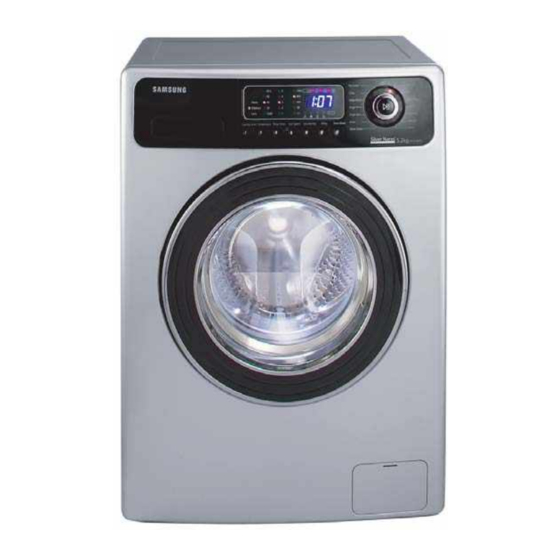
WF7450S9C MODEL CODE : WF7452S9R/YLP WF7450S9C/YLP WF7452S9R/YLW WF7452S9C/YLW WF7450S9C/YLW SERVICE Manual PRODUCT IMAGE THE FEATURE OF PRODUCT SILVER WASH AG+ CALM WASH PREWASH CHILD LOCK EASY IRON Refer to the service manual in the itself (http://itself.sec.samsung.co.kr/) for the more information. -
Page 4: Table Of Contents
Contents 1. PRECAUTIONS ································································································································1-1 1-1. SAFETY NOTES BEFORE INSTALLING ······································································································ 1-1 1-2. SAFETY NOTES FOR INSTALLING ·············································································································· 1-3 1-3. SAFETY PRECAUTIONS ······························································································································ 1-5 2. THE FEATURE OF PRODUCT ·········································································································2-1 2-1. SPECIFICATIONS ·········································································································································· 2-1 2-2. OVERVIEW OF THE WASHING MACHINE ·································································································· 2-2 2-3. - Page 5 Contents 10. SCHEMATIC DIAGRAM ···············································································································10-1 10-1. EMZ (NOT USE IN THIS MODEL) ············································································································· 10-1 10-2. ROLD WF7450S9C,WF7452S9R/C··········································································································· 10-2 11. WIRING DIAGRAM ·······················································································································11-1 11-1. PCB ASSY’ LAYOUT ·································································································································· 11-1 11-2. Connector & Relay Terminals Description (MAIN PCB) ············································································· 11-2 11-3. Connector & Relay Terminals Description (AG-KIT PBA)··········································································· 11-3 11-4.
- Page 6 13. CIRCUIT DESCRIPTIONS 13-1. O VERALL SYSTEM DIAGRAM 13-1...
- Page 7 13. CIRCUIT DESCRIPTIONS 13-2. A C INPUT & POWER CIRCUIT Function - Generates a required DC power of 12V or 5V in case of supplied or disconnected AC power. Description - When AC 220V is applied to CN3, D16 D19 transforms it to DC 300V. - DC 300V is generated for the LVT1 secondary source by IC3 and PC1 turning on/off.
- Page 8 13. CIRCUIT DESCRIPTIONS 13-3. D RIVING SYSTEM CIRCUIT Function - Controls each driving system (VALVE, DOOR S/W, DRAIN-MOTOR) by turning RELAY or TRIAC on/off. Description - MICOM outputs a high signal of 5V from pin # 1 - 7 - Then, pin # 10 to 16 of IC6 and IC8 are electrically grounded (0V). - When pin # 10 to 16 are grounded, this creates an electric potential difference from the 12V that turns on RELAY 5,6,7 and TRIAC2,3,4,5.
- Page 9 13. CIRCUIT DESCRIPTIONS 13-4. M OTOR CIRCUIT Function - Supplies power to the motor and turns it CW/CCW (Right / Reverse direction). Description - The operation of TRIAC1 is the same as that of the driving system. - If the electric potential of R49 is grounded (0V), TRIAC1 turns on. - CN1 detects if the door is locked or unlocked.
- Page 10 13. CIRCUIT DESCRIPTIONS 13-5. S ENSOR DETECTION CIRCUIT Function - Detects signals from the sensor and controls the current system. Description - The water level sensor is connected to pin 4 of CN7. - The frequency of the level sensor changes according to the water amount in the tub. - Then, the frequency is input to MICOM pin 48 for detecting the water amount.
- Page 11 13. CIRCUIT DESCRIPTIONS 13-6. M OTOR TACHO INPUT SYSTEM Function - Detects the current RPM of the motor and controls the output. Description - The motor TACHO sensor is connected to CN10 B-pin. - According to the current RPM of the motor, a square wave is applied to pin 8. - The square wave that is input to TR2 BASE turns the motor on if high (5V), and turns it off if low (0V).
- Page 12 13. CIRCUIT DESCRIPTIONS 13-7. S ILVER NANO SYSTEM Function - Applies the electric current to the silver plate during the water supply and uses the silver water to perform the bacteria- free or sterilization processes. Description - Selects the silver nano feature to operate the system. - Supplies water to the two silver plates AG_B and AG_A.
-
Page 13: Assembly And Disassembly
5. ASSEMBLY AND DISASSEMBLY 5. ASSEMBLY AND DISASSEMBLY 5-1. TOOLS FOR DISASSEMBLY AND ASSEMBLY Tool DESCRIPTION 10 mm Heater (1) Box driver 13 mm Motor (1), Balance (5), 2 holes of each left and right of the 19 mm shock absorber 1 Pulley hole Replaceable for the box driver. -
Page 14: Assembly And Disassembly
5-2. ASSEMBLY AND DISASSEMBLY Warning! To avoid risk of electrical shock, personal injury or death, disconnect the power to the ashing machine Part Name Descriptive Picture How To Do 1. Remove the two screws holding the Top Cover at the back of the unit. ASS’Y COVER 2. - Page 15 5. ASSEMBLY AND DISASSEMBLY Part Name Descriptive Picture How To Do 3. Bend the left side of the control panel to unhook by flat head screwdriver. (Take care not to scratch the surface of the frame- front) 4. Draw the control panel out of the frame-front by gripping the left side of the control panel, pushing the bottom of the control panel up 5.
- Page 16 5. ASSEMBLY AND DISASSEMBLY Part Name Descriptive Picture How To Do Before removing the belt, should be opened the Cover BELT Bottom. 1. Remove the belt before the re-assembly. 2. Ensure the belt is placed on the center of the motor pulley. <Belt Assembly> Hang the belt on the motor pulley() before placing it around the pulley () ...
- Page 17 5. ASSEMBLY AND DISASSEMBLY Part Name Descriptive Picture How To Do 1. Remove the top cover. Water Level Sensor 2. Remove the fixing screws for the water level sensor. 3. Disconnect the water level sensor harness. 4. Disconnect the hose pressure. 5. Replace the water level sensor. 1.
- Page 18 5. ASSEMBLY AND DISASSEMBLY Part Name Descriptive Picture How To Do 1. Insert the flat head screwdriver into the slot on the top of the Cover Filter and lever it down to separate Drain Pump 2. Unscrew the drain filter by turning it counter clockwise.
- Page 19 5. ASSEMBLY AND DISASSEMBLY Part Name Descriptive Picture How To Do 1. Open the Door. 2. Remove the Spring Diaphragm and separate the Diaphragm from the Frame Front. Door S/W - Insert the flat head screwdriver and pry up the spring to remove the Spring Diaphragm. - The Diaphragm could get damaged when taking it out.
- Page 20 5. ASSEMBLY AND DISASSEMBLY Part Name Descriptive Picture How To Do 4. Take out the Heater from the Tub. ( Caution: Be sure to insert the Heater into the Bracket in the Tub. If not, it may cause Heater a fire. And, make sure to have the Packing seating on its place.
-
Page 21: Exploded Views And Parts List
7. EXPLODED VIEWS AND PARTS LIST 7-1. EXPLODED VIEWS OF TOP(FRONT) Note: RC(Recommended), NRC(Not Recommended) in Remark. - Some parts are classifi ed as RC or NRC due to product quality or other reasons. F0125 R0019 C0082 C0075 C0075 C0115 R0124 C0043 A0242... - Page 22 7. EXPLODED VIEWS AND PARTS LIST SVCcod Low Material Description Specifi cation SA/SNA A0242 DC64-01163E INLAY-PANEL WF6522S9R/YLP,PC,T1.0,W60.4, A0328 DC64-01167A PANEL-DRAWER WF-R106NS,ABS,-,-,-,-,BLK,C C0002 DC97-10974R ASSY-PANEL CONTROL WF7452S9R/YLP,BLK/4.5 C0058 DC64-00653A DOOR-LOCK S/W DA,PA6-G,-,H82,W50,-,BLK,2 C0075 DC64-01166A KNOB-ENCODER WF-R106NS,ABS(38208 C0075 DC64-01168A BUTTON-ENCODER WF-R106NS,ABS,-,-,BLK,CHI C0115 MFS-TDF12AB-01 ASSY PCB PARTS(M) MFS-TDF12AB- D0003...
- Page 23 7. EXPLODED VIEWS AND PARTS LIST Memo...
-
Page 24: Exploded Views Of Tub
7. EXPLODED VIEWS AND PARTS LIST 7-2. EXPLODED VIEWS OF TUB U0355 I0043 U0010 U0095 U0307 R0158 U0015 U0023 U0033 U0016 U0355 U0038 U0328 U0029 R0030 R0001 U0035 U0078 R0007 U0012 U0030 U0018... - Page 25 7. EXPLODED VIEWS AND PARTS LIST SVCcod Low Material Description Specifi cation SA/SNA I0043 DC62-10303A HOSE-AIR -,EPDM,ID24,-,-,L130,BLK,SWF-P1 R0001 DC97-01463J ASSY-DRUM F-PJT/SD-PJT/LIFTER,STS430/FIX R0030 DC91-12078C ASSY-WIRE DIAPHRAGM TS-2,Q1636,FE,SW-C,Z R0158 DC62-10305A HOSE-DRAWER TUB -,EPDM,ID35,-,-,L158,BLK U0010 DC66-10176B PULLEY ALDC,-,D297,P1291,ID12.5 U0015 DC31-00002H MOTOR-DRUM HXGP2I,S803J,-,50HZ,-,-,LOW-R U0016 DC62-00007A SEAL-OIL -,NBR(SD25),BLK,-,-,-,P6091/NBU...
-
Page 26: Exploded Views Of Case
7. EXPLODED VIEWS AND PARTS LIST 7-3. EXPLODED VIEWS OF CASE P0001 W0002 W0004 Y0040 W0001 A0115 R0159 W0032 R0158 R0158 R0021 R0159 A0025 A0114 R0027 C0117 I0022 F0027 U0133 U0133 I0003 B0070 A0004 J0013 U0359... - Page 27 7. EXPLODED VIEWS AND PARTS LIST SVCcod Low Material Description Specifi cation SA/SNA A0004 DC63-00689A COVER-FILTER WF-R106NS,ABS,-,-,-,-,-,SIL A0025 DC97-02106A ASSY-FIXER TUB S1005J,SLIM-PJT A0114 DC64-01137A SHUTTER F-SCD,PP,T4.0,W580,L368,WHT,SSEC A0115 DC61-60180A SLEEVE-PLUG NYLON#6,SEW-720DR,-,-,NTR B0070 DC97-02079D ASSY-LEG SBP2,SD455,SD405,FLANG TYPE/25M C0117 MES-AG2MOD-S0 ASSY PCB PARTS(S) MES-AG2MOD-S F0027 DC99-00526C...
- Page 28 7. EXPLODED VIEWS AND PARTS LIST Memo...
- Page 29 8. PARTS LIST (SA) Location. CODE-NO DESCRIPTION SPECIFICATION Q’TY SA/SNA Remark A0034 DC60-40146A BOLT-SPANER OD36,T2.5,L52,FE,FZY,P A0043 DC61-10688A CAP-FIXER SWF-P12,PP(TB53),WHT, A0043 DC61-10688A CAP-FIXER SWF-P12,PP(TB53),WHT, A0067 DC69-01044A CUSHION-CORNER WF6520S9C/YLP,EPS, A0132 DC61-10673A CAP-DRAIN SWF-P12,PP(TB53),WHT, A0198 DC69-00340B BAG PE ALL XQB,PE,0.1,100,100 A0247 DC65-00011A CLAMPER CORE SEW-HW108,NYLON,15,NTR,PO A0362 DC61-40081A...
-
Page 30: Parts List
8. Parts List Location. CODE-NO DESCRIPTION SPECIFICATION Q’TY SA/SNA Remark Z0006 DC97-02412H ASSY-BOLT Q1657 Z0006 DC97-06159B ASSY-BOLT F/R/CWEIGHT BALANCE DC97-11381A ASSY-HOUISING SLIM/F/R MODEL,PP-T DRAWER... - Page 31 2. THE FEATURE OF PRODUCT 2-1. SPECIFICATIONS WASH TYPE FRONT LOADING TYPE NET (W x D x H) 598mm x 404mm x 844mm DIMENSION GROSS (W x D x H) 668mm x 456mm x 890mm WATER PRESSURE 50 kPa ~ 800 kPa 55 kg WEIGHT GROSS...
- Page 32 2. THE FEATURE OF PRODUCT 2-2. OVERVIEW OF THE WASHING MACHINE WATER SUPPLY VALVE AG-KIT PCB SENSOR PRESSURE ASSY DOOR ADJUSTABLE ASSY PUMP POWER CORD BUFFER SPRING WEIGHT-BALANCE DRAIN HOSE PULLEY BELT SHOCK ABSORBER MOTOR...
- Page 33 2. THE FEATURE OF PRODUCT 2-3. THE COMPARATIVE SPECIFICATIONS OF PRODUCT ITEM New(4.5 kg) Old(4.5 kg) WF7452S9R/C MODEL NAME WF-F125AV WF7450S9C CAPACITY (WASHING) 4.5 kg 4.5 kg DRUM CAPACITY 48 ℓ 48 ℓ WASHING MOTOR HXGP2I HXGP2I HEATER (220V) 1900 W...
- Page 34 2. THE FEATURE OF PRODUCT Memo 2-4. ACCESSORY AND OPTION SPECIFICATIONS ITEM DESCRIPTION CODE-NO. Q’TY REMARK HOSE-WATER(C) DC62-10289C BOLT-SPANGER DC60-40146A CAP-FIXER DC61-10688A CAP-FIXER DC67-00208A HOSE-HANGER DC62-10278A...
- Page 35 1. PRECAUTIONS 1-1. SAFETY NOTES BEFORE INSTALLING 1-1-1. How to disassemble the safety apparatus Do not allow consumers to repair the unit themselves, as this may cause personal injury or shorten the product’s working life. 1. Remove the screw of the 2.
- Page 36 1. PRECAUTIONS 1-1-3. Safety Notes before Installing At least two people are needed to Install the product on a solid and Avoid places with direct sunlight unpack or move the product, due fl at surface. and humidity for the installation. to its weight.
- Page 37 1. PRECAUTIONS 1-2. SAFETY NOTES FOR INSTALLING 1-2-1. Grounding Make sure to ground the unit to prevent electric leakage or shock. With a grounded receptacle It does not need an additional grounding. 1-2-2. Water Drainage Hook the drain hose over the Wash Basin or Laundry Tub or plug the end of the drain hose into the Standpipe The end of the drain hose must be passed through the Hose Guide or secured as shown in the picture to prevent it from popping up...
- Page 38 1. PRECAUTIONS 1-2-3. Installation Manner 1. Select an installation place in advance. The distance between the washing machine and the wall must be at least 10cm. 2. Check the balance If you press down or shake any part of the front, left or right side of the washing machine and it still wobbles, adjust the feet again until the machine is standing solidly.
- Page 39 1. PRECAUTIONS 1-3. SAFETY PRECAUTIONS 1. Ensure that users do not repair the product themselves. This may cause harm or shorten the lifetime of the product. 2. Ensure that the power plug is disconnected before performing A/S (especially A/S for electrical parts). Beware of electric shock 3.
- Page 40 1. PRECAUTIONS 16. Do not press any operating buttons using sharp items such as pins, needles etc. This may cause electric shock or mechanical trouble. 17. Check if the product has been evenly and fi rmly installed on the ground. Too much vibration will shorten the lifetime of product.
- Page 41 3. PRODUCT SPECIFICATIONS 3-1. OVERVIEW OF THE CONTROL PANEL 1. Digital graphic display Displays the remaining wash cycle time, all of washing information and error messages. 2. Wash selection button Press the button to select Wash. Wash is available one of 3 wash programs,soak,pre and intensive. 3.
- Page 42 3. PRODUCT SPECIFICATIONS 8. Silver Nano selection button Silver Nano water is supplied in washing as well as the last rinse, featuring sterilization and antibacterial coating. 9. Child Lock selection button This is a button for preventing children from manipulating the washing machine. On/Off - To set the program on: Press the Start/Pause button to turn on the washing machine.
- Page 43 3. PRODUCT SPECIFICATIONS 3-2. PROGRAMME CHART user option) Programme DETERGENT AND ADDITIVES Easy Temp Spin Speed(Max) rpm Delay Cycle Time Iron start (min) (˚C) Prewash Wash Softner WF7452S9R WF7450S9C default WF7452S9C Cotton 1200 1000 1:40 Synthetic 1:10 Shirts 0:50 Delicate Fabrics 0:53 Hand Wash For 0:39...
- Page 44 3. PRODUCT SPECIFICATIONS user option) Programme DETERGENT AND Easy Temp Spin Speed(Max) rpm Delay Cycle Time ADDITIVES start (min) Iron (˚C) Prewash Wash Softner WF7452S9R WF7450S9C default WF7452S9C Daily Wash 0:58 Enzyme 1200 1000 1:40 Baby Cotton 1200 1000 2:01 Mixed Load 1:16 Drain...
- Page 45 3. PRODUCT SPECIFICATIONS 3-3. NEW FEATURES 1. Auto power S/W off function After selecting the function, the auto power S/W off function automatically switches power off for you if you do not press start/pause button for 10 minutes. Until 5 minutes past, After fi nishing the last function, the auto power S/W off function automatically switches power off for you if you do not re-select the course button or manual button.
- Page 46 3. PRODUCT SPECIFICATIONS 9. Water heater Error function (1) This function starts working, when the heater works abnormally. (this function begins sensing the heater 2 minutes later, after the heater operating) (2) The value of the initial thermistor(A1) is compared with that of the thermistor(A2) in 2 minutes. (Y=A2-A1) - For 1 minute , if the variance of temperature(Y) increases more than 40˚C, “HE”...
- Page 47 3. PRODUCT SPECIFICATIONS 11. Unbalance detecting & laundry balance positioning system (1) Just before the hydrating process and just after reversal rotation for balancing laundry position, this function is carried out (2) The initial 6 sec is the period of reversal rotation for balancing laundry position , Drum rotates 50rpm for initial 6 sec (3) Next 8 sec, the rotation increases the speed from 50 rpm to 98 rpm slowly (4) During the next 8 sec, drum rotates at the speed of 98 rpm, the sensor decides the degree of laundry unbalance with TACHO data which is attached to motor...
- Page 48 3. PRODUCT SPECIFICATIONS 3-4. TECHNICAL POINT 1. Motor on/off time at each course Washing 1 Washing 2 Washing 3 Course 1 sec ~ 2 min 59 sec 3 min ~ 12 min 59 sec 13 min ~ On(Cw/Ccw) On(Cw/Ccw) On(Cw/Ccw) Cotton 60min 8/12...
- Page 49 3. PRODUCT SPECIFICATIONS 4. The water level data at each course Default Supplementary Supplementary Supplement times Course water level water - Start water - Stop Washing 23.70 24.20 24.00 Cotton Rinse 23.20 24.20 24.00 Washing 23.00 24.00 23.70 Synthetic Rinse 22.80 24.20 23.90...
- Page 50 3. PRODUCT SPECIFICATIONS 3-5. DESIGNATION OF MAIN COMPONENTS 3-5-1. Normal / Reverse Revolution of Motor and R. P. M. Control <Figure1> <Figure2> <Figure3> (± 7 %) STATOR(5.10) STATOR(5.1) ROTOR(8.9) RACHO(3.4) PROTECTOR(6.7) "H"(mm) Part No. Remark Resistance value 2.08Ω 1.99Ω 38.8Ω DC31-00002H Welling HXGP2I Rated value 220 - 240 V / 50Hz...
- Page 51 3. PRODUCT SPECIFICATIONS 3-5-3. Heater 1) Capacity: AC 230V/1900W 2) Location: Bottom of TUB 3) Function: Raise the water temperature supplied at the wash process. 4) Resistance value: 23~29 Ω 5) Thermal Fuse: 128°C 3-5-4. Detergent tub and water supply value A Detergent tub is composed of housing and 3 drawers .
- Page 52 3. PRODUCT SPECIFICATIONS 3-5-6. Assy-tub Back INNER-BEARING(A) OUT-BEARING(B) OIL-SEAL(C) Assy-Tub Back Remark Ø 20 Ø 17 Ø 50.7 DC97-00214T 3-5-7. Assy- Drum (unit : mm) BUSH-SHAFT(C) Assy-Drum Remark Ø 20 Ø 17 Ø 25 DC97-01463Q 3-5-8. Assy-pump Drain 1) Capacity : AC 230V 34W 2) Location : Front bottom(R) 3) Resistance : 160Ω...
- Page 53 14. REFERENCE INFORMATION 14-1. M ODEL NAME 14-1...
- Page 54 14. REFERENCE INFORMATION 14-2. REFERENCE INFORMATION 1) ASSY-MAIN PCB (Imbalance Sensor) To prevent the laundry from gathering on one side of the tube causing noise and vibration, the washing machine uses an imbalance detection device that evenly disentangles the laundry before the hydrating cycle starts. 2) DOOR-LOCK S/W Prevents the door from being opened while a cycle is in progress.
- Page 55 14. REFERENCE INFORMATION 14-3. F ABRIC CARE CHART Resistant material Can be ironed at 100 ûC max Delicate fabric Do not iron Item may be washed at 95 C Can be dry cleaned using any solvent Dry clean with perchloride, lighter fuel, Item may be washed at 60 C pure alcohol or R113 only Dry clean with aviation fuel,...
- Page 56 14. REFERENCE INFORMATION 14-4. E LECTRICAL WARNINGS To reduce the risk of fire, electrical shock, and other injuries, keep these safety precautions in mind: Operate the appliance only from the type of power source indicated on the marking label. If you are not sure of the type of power supplied to your home, consult your appliance dealer or local power company. Use only a grounded or polarized outlet.
- Page 57 14-5. Q & A Solut ion Type Part Situation Before consu lting cause Management method Door is not opened during washing. For models applied DRUM Being opened & closed bad/Being AS rerecomm with the boiling or drying the door will not open until the interior appearance part In case of a cover not being opened or closed WASHER...
- Page 58 14. REFERENCE INFORMATION Solut ion Type Part Situation Before consu lting cause Management method Disconnect the coupler and reassemble it. It had better to DRUM water leakage water being leaked at water supply General It may be occurred when it is pushed out due to assemble by yourself because the engineer’s visit for service will be WASHER related...
- Page 59 14. REFERENCE INFORMATION Solut ion Type Part Situation Before consu lting cause Management method 1E :front loading DRUM AS rerecomm It may happen when there is a trouble in air hose washing machine E7 Water level sensor ERR In this case you are recommended our engineer’s inspection. WASHER ended or water level sensor.
- Page 60 14. REFERENCE INFORMATION Solut ion Type Part Situation Before consu lting cause Management method Did the rinse agent drain immediately or part to put the rinse is clogged after putting the rinse agent? DRUM General It may appear when the rinse agent remains to rinsing related Rinse being not put in tub The rinse agent does not drain only when putting it up...
- Page 61 14. REFERENCE INFORMATION 14-5. Q & A - ABOUT ERROR No trouble Trouble Display Meaning Cause Solution method Over fl ow error. 1. Is the water supply valve bad? 1.Is the winding of the water supply continuous(4.2kω)? (If water level frequency is sensed over fl ow 15.01khz -21.00khzin 5sec, this error will occur) 2.
- Page 62 14. REFERENCE INFORMATION No trouble Trouble Display Meaning Cause Solution method Cause Solution method The water is not supplied and water level does not reach the preset 1.Is the tap open? 1.Open the tap. 1.Is the water supply valve bad? 1.Is the winding of the water supply continuous(4.2kω)? level.
- Page 63 Samsung Electronics Co.,Ltd. 416, Maetan-3Dong, Yeongtong-Gu, Suwon City, This Service Manual is a property of Samsung Electronics Gyeonggi-Do, Korea, 443-742 Co.,Ltd. Printed in Korea Any unauthorized use of Manual can be punished under P/N: DC68-02675A-02 applicable International and/or domestic law.
- Page 64 10. SCHEMATIC DIAGRAM 10. SCHEMATIC DIAGRAM 10-1. EMZ (NOT USE IN THIS MODEL) 10-1...
- Page 65 10. SCHEMATIC DIAGRAM 10-2. ROLD WF7452S9R/C,WF7450S9C 10-2...
- Page 66 6. TROUBLE DIAGNOSIS 6-1. TROUBLE DIAGNOSIS As the micom wash machine is confi gured of the complicate structure, there might be the service call. Below information is prepared for exact trouble diagnosis and suitable repair guide. Caution for the Repair and Replacement Please follow below instruction for the trouble diagnosis and parts replacement.
- Page 67 6. TROUBLE DIAGNOSIS Item Cause and treatment - Is the PCB connector connected well? - Is the voltage normal? - Is the power supply plug connected well? The power is not supplied - Is the noise fi lter connected well? - Is the secondary output of the power su pply transformation normal? - Is the fuse disconnected? (option) If above points are not found, the PCB assembly is out of order.
- Page 68 6. TROUBLE DIAGNOSIS 6-2. PROBLEM CHECKING AND METHOD OF PCB 6-2-1. The Part Of Power Source NO Power On The Voltage Of Betweenⓐand ⓑIs Check The Trans As Big As 12V? The Voltage Of Betweenⓒand ⓓ Is Check The Condenser(CE3) As Big As 12V? The Voltage Of Exchange IC5 (7805) And...
- Page 69 6. TROUBLE DIAGNOSIS 6-2-3. Interrupt Part Check The Curve Check Power source Output Of ⓐ ? Check The Micom Check PC2, TR4, R54 Number 9? Check The Part Of Oscillator 6-2-4. Checking The Part Of An Oscillator When The Micom 2, 3 Check Resonator Check, The Value Is 16Mhz?
- Page 70 6. TROUBLE DIAGNOSIS 6-2-5. Check The Part Of Buzzer Check The Part Of Power Source ⓐ Part Confi rm DC12V ? Exchange BUZZER1, Check IC8, R69, R29...
- Page 71 6. TROUBLE DIAGNOSIS 6-2-6. Driving Part Checking Confi rm The Output Of DC5V, When The Every Part Of Micom Number Check, According To The Some Problem Condition ex) When The Drain Is Not Operating But Pump Motor Is Operating, Check The 5Voltage Of Micom Micom Number, 31 Is Micom Bad 5Voltage?
- Page 72 6. TROUBLE DIAGNOSIS 6-2-7. Confi rm The Driving Part Of Motor Check BD1, TRIAC1 Motor Is Not Spinning Motor Is Not Turning Check RELAY3 (RY3) Right And Left Check The Tacho Part 6-2-8. Checking The Tacho Part Have The Motor Turn In Hand Check The Surroundings Is The Rectangular Circuit And TR5...
- Page 73 6. TROUBLE DIAGNOSIS 6-3. DETAILED DIAGNOSIS 1. Driving Compartment Test Mode A. Hold down the 2 and the 3 buttons simultaneously and then press the Power button 11. (All of the LEDs light up and the display shows t1 in 2 seconds.) B.
- Page 74 10. SCHEMATIC DIAGRAM 10. SCHEMATIC DIAGRAM 10-1. EMZ (NOT USE IN THIS MODEL) 10-1...
- Page 75 10. SCHEMATIC DIAGRAM 10-2. ROLD WF7452S9R/C,WF7450S9C 10-2...
- Page 76 7. EXPLODED VIEWS AND PARTS LIST 7-1. EXPLODED VIEWS OF TOP(FRONT) Note: RC(Recommended), NRC(Not Recommended) in Remark. - Some parts are classifi ed as RC or NRC due to product quality or other reasons. F0125 R0019 C0082 C0075 C0075 C0115 R0124 C0043 A0242...
- Page 77 7. EXPLODED VIEWS AND PARTS LIST SVCcod Low Material Description Specifi cation SA/SNA A0242 DC64-01163E INLAY-PANEL WF6522S9R/YLP,PC,T1.0,W60.4, A0328 DC64-01167A PANEL-DRAWER WF-R106NS,ABS,-,-,-,-,BLK,C C0002 DC97-10974R ASSY-PANEL CONTROL WF7452S9R/YLP,BLK/4.5 C0058 DC64-00653A DOOR-LOCK S/W DA,PA6-G,-,H82,W50,-,BLK,2 C0075 DC64-01166A KNOB-ENCODER WF-R106NS,ABS(38208 C0075 DC64-01168A BUTTON-ENCODER WF-R106NS,ABS,-,-,BLK,CHI C0115 MFS-TDF12AB-01 ASSY PCB PARTS(M) MFS-TDF12AB- D0003...
- Page 78 7. EXPLODED VIEWS AND PARTS LIST Memo...
- Page 79 7. EXPLODED VIEWS AND PARTS LIST 7-2. EXPLODED VIEWS OF TUB U0355 I0043 U0010 U0095 U0307 R0158 U0015 U0023 U0033 U0016 U0355 U0038 U0328 U0029 R0030 R0001 U0035 U0078 R0007 U0012 U0030 U0018...
- Page 80 7. EXPLODED VIEWS AND PARTS LIST SVCcod Low Material Description Specifi cation SA/SNA I0043 DC62-10303A HOSE-AIR -,EPDM,ID24,-,-,L130,BLK,SWF-P1 R0001 DC97-01463J ASSY-DRUM F-PJT/SD-PJT/LIFTER,STS430/FIX R0030 DC91-12078C ASSY-WIRE DIAPHRAGM TS-2,Q1636,FE,SW-C,Z R0158 DC62-10305A HOSE-DRAWER TUB -,EPDM,ID35,-,-,L158,BLK U0010 DC66-10176B PULLEY ALDC,-,D297,P1291,ID12.5 U0015 DC31-00002H MOTOR-DRUM HXGP2I,S803J,-,50HZ,-,-,LOW-R U0016 DC62-00007A SEAL-OIL -,NBR(SD25),BLK,-,-,-,P6091/NBU...
- Page 81 7. EXPLODED VIEWS AND PARTS LIST 7-3. EXPLODED VIEWS OF CASE P0001 W0002 W0004 Y0040 W0001 A0115 R0159 W0032 R0158 R0158 R0021 R0159 A0025 A0114 R0027 C0117 I0022 F0027 U0133 U0133 I0003 B0070 A0004 J0013 U0359...
- Page 82 7. EXPLODED VIEWS AND PARTS LIST SVCcod Low Material Description Specifi cation SA/SNA A0004 DC63-00689A COVER-FILTER WF-R106NS,ABS,-,-,-,-,-,SIL A0025 DC97-02106A ASSY-FIXER TUB S1005J,SLIM-PJT A0114 DC64-01137A SHUTTER F-SCD,PP,T4.0,W580,L368,WHT,SSEC A0115 DC61-60180A SLEEVE-PLUG NYLON#6,SEW-720DR,-,-,NTR B0070 DC97-02079D ASSY-LEG SBP2,SD455,SD405,FLANG TYPE/25M C0117 MES-AG2MOD-S0 ASSY PCB PARTS(S) MES-AG2MOD-S F0027 DC99-00526C...
- Page 83 7. EXPLODED VIEWS AND PARTS LIST Memo...
- Page 84 8. PARTS LIST (SA) Location. CODE-NO DESCRIPTION SPECIFICATION Q’TY SA/SNA Remark A0034 DC60-40146A BOLT-SPANER OD36,T2.5,L52,FE,FZY,P A0043 DC61-10688A CAP-FIXER SWF-P12,PP(TB53),WHT, A0043 DC61-10688A CAP-FIXER SWF-P12,PP(TB53),WHT, A0067 DC69-01044A CUSHION-CORNER WF6520S9C/YLP,EPS, A0132 DC61-10673A CAP-DRAIN SWF-P12,PP(TB53),WHT, A0198 DC69-00340B BAG PE ALL XQB,PE,0.1,100,100 A0247 DC65-00011A CLAMPER CORE SEW-HW108,NYLON,15,NTR,PO A0362 DC61-40081A...
- Page 85 8. Parts List Location. CODE-NO DESCRIPTION SPECIFICATION Q’TY SA/SNA Remark Z0006 DC97-02412H ASSY-BOLT Q1657 Z0006 DC97-06159B ASSY-BOLT F/R/CWEIGHT BALANCE DC97-11381A ASSY-HOUISING SLIM/F/R MODEL,PP-T DRAWER...
Need help?
Do you have a question about the WF-F125AV and is the answer not in the manual?
Questions and answers