
Related Manuals for H3C PSR1400-A


Summary of Contents for H3C PSR1400-A
- Page 1 H3C PSR1400-A & PSR1400-D Power Module User Manual New H3C Technologies Co., Ltd. http://www.h3c.com Document version: T2-08010Q-20201205-C-1.06...
- Page 2 All rights reserved No part of this manual may be reproduced or transmitted in any form or by any means without prior written consent of New H3C Technologies Co., Ltd. Trademarks Except for the trademarks of New H3C Technologies Co., Ltd., any trademarks that may be mentioned in this document are the property of their respective owners.
-
Page 3: Table Of Contents
Schematic Views ······································································ 2 Specifications ··········································································· 4 Status LEDs ·············································································· 5 Status LEDs of the PSR1400-A ··········································· 5 Status LEDs of the PSR1400-D ··········································· 7 Power Module Installation and Removal ············ 9 Installing and Removing a Power Module ································· 9 Installing a Power Module ··················································... -
Page 4: Introduction
Introduction The PSR1400-A is a built-in power module with AC input and DC output while the PSR1400-D is a built-in power module with DC input and DC output. The PSR1400-D can provide the device with both system power and PoE power, which can be controlled through separate switches. -
Page 5: Schematic Views
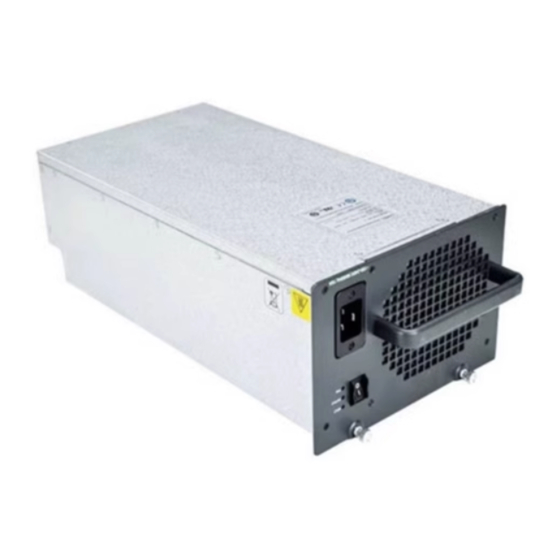
Schematic Views Figure 1 Schematic view of the PSR1400-A (1) Captive screws (2) Power switch (3) Status LEDs (4) AC socket (5) Power cable retention clip (6) Power module handle... - Page 6 Figure 2 Schematic view of the PSR1400-D (1) Captive screws (2) PoE monitoring port (3) Status LEDs (4) Negative (–) terminal of DC input (5) Positive (+) terminal of DC input (6) Power module handle (7) System power switch (8) PoE power switch The PSR1400-D can provide both system power and PoE power outputs.
-
Page 7: Specifications
The PoE power output can be used both for power supply of PoE-powered devices and for auxiliary power supply of devices that do not support PoE. For details, refer to the corresponding installation manuals. Specifications Table 2 Technical specifications for the PSR1400-A and PSR1400-D Item Specifications PSR1400-A: 100 VAC to 240 VAC;... -
Page 8: Status Leds
-40~70°C temperature Status LEDs Status LEDs of the PSR1400-A The PSR1400-A has three red/green status LEDs, which indicate the input and output statuses of the power module and the working status of the power module fan, respectively. Table 3 describes the colors and working status of the three LEDs in... - Page 9 Table 3 Description of LEDs on the PSR1400-A Color/status Meaning No power input is present. INPUT Green The power input is normal. The power input is abnormal. No power input is present. Green The power output is normal. The power switch is off.
-
Page 10: Status Leds Of The Psr1400-D
Table 3 describes the colors and working status of the three LEDs in different cases. Table 4 Description of LEDs on the PSR1400-A Status Meaning No power input is present. The power input is normal but the system switch is in the OFF position. - Page 11 You can use the same method to handle the alarms on both the PSR1400-D (In case of an alarm, the OUTPUT or PoE LED turns red) and PSR1400-A. • Do not turn on and off the power switch too frequently. After turning off the power switch, wait at least 30 seconds before turning it on again.
-
Page 12: Power Module Installation And Removal
Installing and Removing a Power Module This section describes how to install and remove a PSR1400-D power module. You can install and remove a PSR1400-A power module in a similar way. You need to prepare the tools that you need to use to install or... -
Page 13: Installing A Power Module
Figure 5 Install/remove a PSR1400-D power module Installing a Power Module Wear an ESD-preventive wrist strap and take a new power module out of its package. Check that the input mode of the power module is correct. Grasp the handle of the module with one hand and hold the module bottom with the other. -
Page 14: Removing A Power Module
Tighten the captive screws with a No. 1 Phillips screwdriver. CAUTION: If the captive screws cannot be tightened, check whether the power module is properly installed. Removing a Power Module Remove a power module in the opposite way you install it: Wear an ESD-preventive wrist strap and loosen the captive screws on the power module. -
Page 15: Connecting The Ac Power Cord
Plug the other end into the AC power socket strip of the AC mains. CAUTION: Since typically 10 A busbars are available in equipment rooms but the PSR1400-A power module requires a 16 A power cable (AC), you need to use a 16 A busbar. -
Page 16: Connecting The Dc Power Cables
Connecting the DC Power Cables Figure 7 Connect the DC power cables Terminal block Flat washer Spring washer Flat washer Fastening nut To connect the PSR1400-D power module, proceed as follows: Loosen the fastening screws on the protection cover with a No. 1 Phillips screwdriver and remove the protection cover. - Page 17 Put the flat washers and spring washer on the wiring terminal in turn and screw up the fastening nut with the M6 socket wrench. Repeat this step for the other three terminals. Put the protection cover on the wiring terminals and tighten the fastening screws.
Need help?
Do you have a question about the PSR1400-A and is the answer not in the manual?
Questions and answers