
Related Manuals for H3C PSR2800-ACV


Summary of Contents for H3C PSR2800-ACV
- Page 1 H3C PSR2800-ACV Power Module User Manual New H3C Technologies Co., Ltd. http://www.h3c.com Document version: T2-08010R-20201205-C-1.04...
- Page 2 All rights reserved No part of this manual may be reproduced or transmitted in any form or by any means without prior written consent of New H3C Technologies Co., Ltd. Trademarks Except for the trademarks of New H3C Technologies Co., Ltd., any trademarks that may be mentioned in this document are the property of their respective owners.
-
Page 3: Table Of Contents
Contents Introduction ························································ 1 Schematic View ········································································ 2 Specifications ··········································································· 3 Status LEDs ·············································································· 4 Power Module Installation and Removal ············ 6 Installing and Removing a Power Module ································· 6 Installing a Power Module ···················································· 7 Removing a Power Module ·················································· 8 Connecting and Disconnecting the AC Power Cords·················... -
Page 4: Introduction
Introduction The PSR2800-ACV is a built-in power module with AC input and DC output. It can provide the device with both system power and PoE power, which can be controlled through separate switches. Table 1 Features of the PSR2800-ACV power module... -
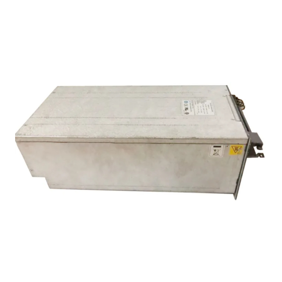
Page 5: Schematic View
(6) PoE socket (7) Power cord retention clip (8) PoE switch (9) Power module handle The PSR2800-ACV can provide both system power and PoE power outputs. The upper switch (callout (4) in Figure 1) is used to control the output of the entire power supply system, while the lower switch... -
Page 6: Specifications
The PoE power can be used both for power supply of PoE-powered devices and for auxiliary power supply of devices that do not support PoE. For details, refer to the corresponding installation manuals. Specifications Table 2 Technical specifications for the PSR2800-ACV power module Item Specifications 100 VAC to 240 VAC;... -
Page 7: Status Leds
Status LEDs The PSR2800-ACV power module has five red/green status LEDs: INPUT, OUTPUT, FAN, PoE INPUT, and PoE OUTPUT. The PSR2800-ACV power module can provide PoE only when the system power output is normal. Table 3 describes the colors and working status of the five LEDs in different cases. - Page 8 Color/ Meaning status No system power input is present. Green The power module fan works normally. The system switch is in the OFF position. The power module fan is faulty (The power module takes a self-protection action and stops power output two seconds after the fan fails).
-
Page 9: Power Module Installation And Removal
Power Module Installation and Removal When installing or removing a power module be sure to follow the sequence shown in Figure 2 Figure Figure 2 Flow chart for installing a power module Turn on the Connect the Install the power switch power cable power module Figure 3 Flow chart for removing a power module... -
Page 10: Installing A Power Module
Follow these steps to install the PSR2800-ACV power module: Put on an ESD-preventive wrist strap. Take out the PSR2800-ACV power module out of its package. With one hand grasping the handle of the power module and the other holding the bottom, insert the power module along the guide rails into the chassis until it snaps into the backplane connector. -
Page 11: Removing A Power Module
If the captive screws cannot be tightened, check whether the power module is properly installed. Removing a Power Module Follow these steps to remove the PSR2800-ACV power module: Put on an ESD-preventive wrist strap. Loosen the captive screws on the power module with a No. 1 Phillips screwdriver. -
Page 12: Connecting And Disconnecting The Ac Power Cords
Connecting and Disconnecting the AC Power Cords The following describes how to connect a power cable. To disconnect a power cable, follow the inverse order. When connecting and disconnecting power cables, check that the power switch is in the OFF position. Connecting the AC Power Cords The following describes how to connect the system power cord. - Page 13 Plug the other end into the AC power socket strip of the AC mains. CAUTION: Since typically 10 A busbars are available in the equipment room but the PSR2800-ACV power module requires a 16A power cable (AC), you need to use a 16 A busbar.
Need help?
Do you have a question about the PSR2800-ACV and is the answer not in the manual?
Questions and answers