
Related Manuals for MLT FS-16-25


Summary of Contents for MLT FS-16-25
- Page 1 Automated Slide Stainer FS-16-25 Instruction for Use Read carefully before working with the stainer Always keep this Instructions for Use near the stainer V1.1 English – 10.02.2021 Dubna...
- Page 2 Revision history Revision Effective date Change Written by 22.01.2021 Draft Bezrukov A.V. Kutepov M.V. 10.02.2021 For CE marking Bezrukov A.V.
- Page 3 ALWAYS KEEP THIS INSTRUCTION FOR USE NEAR THE STAINER. MLT LLC reserves the right to change technical specifications as well as manufacturing processes without prior notice. Only this way is it possible to continuously improve the technology and manufacturing techniques. The information on important changes is added to the technical file of the device and is published on the manufacturer’s website www.mlt.ru.
-
Page 4: Table Of Contents
Table of contents 1 Important information ......................5 1.1 Used symbols and indications ..................5 1.1.1 Warning words..................... 5 1.1.2 Symbols....................... 6 1.1.3 Stainer label......................7 1.1.4 Designation of menu sections, touch screen buttons, and operational actions..8 1.2 Intended use ....................... - Page 5 3 Safety measures when handling HFL and CL ............. 57 4 Actions in case of fire ....................58 APPENDIX B. List of reagents FS-16-25* ................ 59 APPENDIX С. Example of developing the <DEMO> program ........... 59 Protocol of the <DEMO> program and its configuration ..........60 Listing of the <DEMO>...
-
Page 6: Important Information
This instruction for use includes important information related to the operating safety and maintenance of the automated slide stainer FS-16-25 (further – Stainer). The instruction for use is an important part of the product. It must be read carefully and completely before setup and prior use of the Stainer and must be kept near the device at all times. -
Page 7: Symbols
1.1.2 Symbols. Symbol Name of the symbol Location, designation Lid of the Stainer. A warning about handling of toxic Warning, danger and corrosive reagents, about the necessity to use protective equipment. Lid of the Stainer. A warning about the handling of Fire hazard highly flammable liquids. -
Page 8: Stainer Label
Open here Operational documentation. Instruction for use, label on the rear panel of the Stainer, labels on the packing box of the device. A MLT LLC logo stylized image of the manufacturing company’s name. 1.1.3 Stainer label. The label containing the Stainer’s name, its serial number, the year of manufacture and other information is situated at the rear panel of the device. -
Page 9: Designation Of Menu Sections, Touch Screen Buttons, And Operational Actions
1.1.4 Designation of menu sections, touch screen buttons, and operational actions. Menu sections are designated with capital letters between double angle quotation marks, e.g., «PROCESS», «SERVICE», «CONFIGURATION», etc. Touch screen buttons are designated in the text as inscriptions in capital letters placed in a frame, e.g., ENTER, YES, STOP. -
Page 10: Intended Use
1.2 Intended use The automated slide stainer FS-16-25 is a device for IN VITRO diagnostics. The device is designated for the staining of biological preparations on slides. The primary intended use is histology (particularly – H&E technique) and cytology (particularly –... -
Page 11: Safety
2 Safety 2.1 General safety statements This Stainer has been developed, manufactured, and tested under safety requirements for electrical laboratory devices. To maintain a safe technical state of the Stainer, the operator must observe all requirements of this instruction for use. If the instructions are not followed, then the protection provided by the device may be impaired. - Page 12 FORBIDDEN TO OPERATE THE STAINER, IF IT IS NOT CONNECTED TO VENTILATION OR BEYOND EXHAUST HOOD. Highly flammable liquids, such as spirits, spirit-based dyes, xylene or xylene substitutes may be used during an operation. FORBIDDEN TO INSTALL THE STAINER IN DIRECT VICINITY OF A FLAME OR IGNITABLE SPARKS.
-
Page 13: General Characteristics
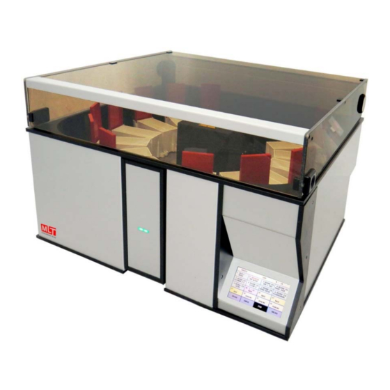
3. General characteristics 3.1 Description of Stainer 3.1.1 Construction of Stainer. The Stainer consists of a technological unit (5) with a working chamber and a lid (1) and a control unit (3) with a touch-screen (4). Figure 2. Front view of the Stainer. 1 –... - Page 14 Figure 3. Rearview of the Stainer. 1 – transparent lid; 7 – exhaust water outlet; 8 – exhaust ventilation grid with an outlet* 9 – tap water inlet; 10 – Stainer label with a serial number, manufacturing year; 11 – power supply inlet**;12 –...
- Page 15 Figure 4. Top view of the Stainer, working chamber of the technological unit. 14 – drying station; 15 – arm of manipulator; 16 – trough with a rack inside; 17 – rack with slides; 18 – handle of rack; 19 – manipulator housing; 20 – upper panel of Stainer; 21 – flow- through trough;...
-
Page 16: Accessories: Troughs And Racks
3.1.2 Accessories: troughs and racks. The Stainer is supplied with RV-25 racks for 25 slides. Figure 5. Stainless steel rack RV-25 with slides. 17 – rack; 18 – handle of the rack The Stainer is supplied with two types of troughs: TV-25-POM –... -
Page 17: Micro Sd Card And Micro Sd Card Slot
TV-25-PP – a polypropylene trough (color: either white or natural half- transparent) for RV-25 racks; recommended when handling aqueous solutions; spirits; and acetone. Recommended volume of liquid in troughs: when there are 25 slides loaded into the rack – 210 ± 10 ml. when there are 12 slides loaded into the rack –... - Page 18 technological operations are carried out (fixation, staining, washing, drying, blotting and so on). Operation duration, reagent, and station, in which the operation is performed, are programmable and changeable. Control and programming are performed with a color touch- screen display. Programming functions include not only the consequence and duration of technological operations but also their parameters and modes.
-
Page 19: Technical Data
3.2 Technical data Number of combined stations Number of upload-unload stations (gateway) Number of drying stations Number of washing stations (with a flow-through trough) Size of slides* 76 26 х 1,0 mm Stained part of a slide ~ 26 × 55 mm Capacity of RV-25 racks Heating modes of the drying station strong/weak... -
Page 20: Delivery Set
3.4 Delivery set A standard delivery set includes: Device Product code Quantity 266012.006 Automated slide stainer FS -16-25 Accessories RV-25 rack for slides (for 25 slides) 06.01.00 TV-25-PP trough for reagents with a lid 06.06.00 TV-25-POM trough for reagents with stainless steel lid 06.06.00-01 Blotter 07.10.00... -
Page 21: Unpacking And Installation Of Stainer
4. Unpacking and installation of Stainer 4.1 Site requirements The Stainer must be placed on a solid horizontal surface with the dimensions min. 0,6 m long and 0,6 m wide. A grounded socket for connection to power must be situated not father from the installation site than the length of the cable (1,5 m). - Page 22 IT IS RECOMMENDED TO KEEP THE ORIGINAL PACKING OF THE STAINER AND ACCESSORIES. CAUTION! ANY DEVICE, ITS PART, OR ACCESSORY, WHICH IS RETURNED TO MLT LLC, OR WHICH IS IN NEED OF MAINTENANCE AT THE OPERATION SITE, MUST BE APPROPRIATELY CLEANED AND DISINFECTED. 5.4.2)
-
Page 23: Connection Of Stainer
4.3 Connection of Stainer Place the Stainer on the installation site. If necessary, align the device in a horizontal plane with the help of screw-type feet (12) (Fig. 3) 4.3.1 Electric connection. The Stainer is connected to the electric socket with a power cord, which is supplied with the device. - Page 24 CAUTION! BEFORE CONNECTION, CHECK FOR A BACK-FLOW VALVE AT THE PIPE STUB OF SIPHON; IF THERE IS ONE – REMOVE IT, BECAUSE THE WATER DRAIN, FLOWS NATURALLY. CAUTION! THE DRAIN HOSE MUST NOT BE KINKED, BENT, OR PINCHED CAUSING HOSE DAMAGE OR RESTRICTING WATER FLOW. CAUTION! THE EXHAUST WATER OUTLET MUST BE LOCATED HIGHER THAN THE CONNECTION POINT OF THE HOSE TO THE DRAIN SYSTEM AND HIGHER THAN...
- Page 25 CAUTION! MAKE SURE THERE ARE NO LEAKS IN THE WATER SUPPLY AND IN THE DRAIN SYSTEMS AND THAT THERE ARE NO BENDS AT THE DRAIN HOSE BEFORE STARTING THE OPERATION. CAUTION! WHEN THE WORK IS FINISHED, IT IS RECOMMENDED TO TURN OFF THE TAP.
-
Page 26: Operation And Control Of Functioning
5. Operation and control of functioning 5.1 Main menu, menu structure Operation and functioning control of the Stainer is carried out with a 480 x 272-pixel color touch screen. When the Stainer is switched on, it starts self-testing, and a splash screen with a manufacturer’s (or dealer’s) logo appears on the touch screen (Fig. -
Page 27: Menu Section "Techniques": Programming Of New Techniques, Editing Of Parameters Of Previously Downloaded Techniques
troughs with reagents in the working chamber following the protocol of technological program, and check the expiry date of reagents. The bottom part of the screen has the following buttons: TECHNIQUES START OF PROCESS CONFIGURATION TECHNIQUES – to switch to the menu section «TECHNIQUES» (choice of a technological program from the available ones, correction of parameters of a program, and programing a new technological program). - Page 28 a respective name. Pressing the button DEMO starts a demonstration program for acquaintance with the Stainer and checks of its working capacity. The bottom part of the screen has the following buttons: MAIN MENU ◄► MAIN MENU – to switch back to the main screen. ◄►...
- Page 29 Enter the name of the new program and press the button ENTER to switch to the screen of program editing. If the entered name is unique, i.e., it has not been entered before, a template of a new program (Fig. 15) with the already given number of operations appears on the screen.
- Page 30 - Set an operational <REGIME> for the manipulator (<IMMERSION> or <DIPPING>). To change the regime, touch the screen at the spot of the needed parameter. Regime <IMMERSION>. The regime, in which a rack with slides is immersed into the reagent and is kept in it until the end of a technological operation. Regime <DIPPING>.
- Page 31 Figure 17. NEW PIN entering screen. CAUTION! A CONFIRMATION IS OBLIGATORY FOR SAVING A NEW PROGRAM AND FOR SAVING CHANGES. An offer to save a new program (Fig. 18) appears on the screen after pressing the button START OF PROCESS in the main menu. Figure 18.
- Page 32 <INCORRECT PIN FORMAT DEFAULT SETTED PIN IS 255 TOUCH THE SCREEN TO CONTINUE> The Stainer allows you to wright and save up to 32 programs. All programs, including the preprogrammed ones (factory programs), can be edited. An edited program can be saved under a new name (as a new program), herewith a message will appear on the screen: <SAVE CHANGED PROGRAM...
-
Page 33: Menu Section "Configuration": Programming And Control Of The Configuration, Performing Of Service Functions
If you press the button NO, the edited program will be launched, but after you switch off the Stainer, the changes will not be saved. If the newly entered PIN was incorrect, after pressing the button START OF PROCESS on the screen will be message: <INCORRECT PIN IS ENTERED ALL CHANGES MADE TO THE PROGRAM ARE CANCELED TOUCH THE SCREEN TO RETURN TO THE MAIN MENU>... - Page 34 In the middle part of the screen, there is a configuration view of the Stainer for a chosen program, represented by 16 rectangular buttons, which correspond to 16 stations. The buttons for technological stations are colored in blue. They contain the following information: the number of a station, the appointed reagent, the value <RESOURCE>...
- Page 35 Figure 21. Configuration of station No. 1 <DRYER>. < STATION APPLICATION > parameter < DRYING > – not editable. <REAGENT> parameter <AIR> – not editable. <MODE> parameter <HEATING++> – modes of heating of air in the drying station. Pressing the button switches between modes <HEATING+> (weak) and <HEATING++>...
- Page 36 <RESOURCE LIMIT> – not editable (only for station <FLOW-THROUGH>). <DELAY> – editable parameter: the duration of a rack’s delay in the upper position after rising from a trough (0-99 seconds, default value is 10). Stations No. 3-8, 9-16 can allocate troughs with reagents or racks, these stations must have respective application values: <TECHNOLOGICAL>...
-
Page 37: Setting The Interval Of The Introduction Of Racks Into The Process
CAUTION! WHEN THE VALUE REACHES ZERO, A MESSAGE APPEARS ON THE SCREEN, WARNING ABOUT THE EXHAUSTION OF RESOURCE LIMIT OF A REAGENT: <RESOURCE LIMIT OF TROUGH # XX IS EXHAUSTED> It gives the opportunity to duly change reagent in the respective trough. To continue the process, press the button CANCEL. - Page 38 Figure 24. Entering the duration of the interval. CAUTION! WHEN CALCULATING AN OPTIMAL INTERVAL, IT IS VITAL TO TAKE INTO CONSIDERATION THAT THE TIME, SPENT FOR TRANSFERRING A RACK AND FOR RACK’S DELAY UNDER A TROUGH FOR DRAINING OF LIQUID, IS NOT ADDED TO THE VALUE OF THE INTERVAL BY DEFAULT.
-
Page 39: Menu Section "Service". Performing Of Service Functions
5.3.2 Menu section «SERVICE». Performing of service functions. To access the menu of service functions, press the button SERVICE (Fig. 25): Figure 25. Service functions menu. POSITIONING TEST – check of the working capacity of the Stainer and its accessories (test positioning program). - Page 40 TOTAL FIRMWARE RELOADING - is intended to set the mode of firmware reloading by changing data in SD card. The data in SD card is changed with «FASTAINER firmware editor» PC software. (Appendix DEMO WITH UPLOADING DEMO – is intended to set the DEMO program mode: one- time with uploading of rack or cyclic PROGRAM.
-
Page 41: Menu Section "Process": Loading And Unloading Of Racks. Processing Of Racks With Slides According To A Given Technological Program
5.4 Menu section «PROCESS»: loading and unloading of racks. Processing of racks with slides according to a given technological program After the technological program is selected and the troughs with reagents are properly arranged, press the button START OF PROCESS in the Main menu. -
Page 42: Automated Loading And Unloading Of Racks Through The Gateway
5.4.2 Automated loading and unloading of racks through the gateway. After pressing the button START OF PROCESS, the gateway opens, and the message appears on the screen: Figure 27. Menu section «PROCESS» – automated loading of racks. Simultaneously with the message appearing, the manipulator starts moving. The Stainer checks the readiness for the loading of the nearest parking station. -
Page 43: Automated Loading And Unloading Of Racks Through The Manipulator
Continuation of loading of racks. Press the button CONTINUE. The gateway places the rack at station #9. The manipulator takes the rack from station #9 and places it at the nearest unoccupied parking station automatically. After loading of the rack is completed, the gateway opens, and a message appears on the screen: <PUT THE RACK IN THE GATEWAY AND PRESS THE BUTTON... - Page 44 Simultaneously with the message, the manipulator starts moving. The Stainer checks the readiness for loading of the nearest parking station and brings the manipulator arm to a halt above station No. 9. Open the lid of the Stainer If the lid is open, a message requiring closing the lid will appear Figure 30.
-
Page 45: Loading Of Racks During The Performance Of A Technological Program
Completion of loading of racks. CAUTION! CLOSE THE LID OF THE WORKING CHAMBER and press the button FINISH. After that, the Stainer starts to perform the technological program. If the lid is open, a message requiring closing the lid will appear. When a technological program is in progress, stations and their state are shown on the screen. -
Page 46: Status Screen During A Technological Process
. The gateway opens, and the message appears on the screen: <PUT THE RACK IN THE GATEWAY AND PRESS THE BUTTON <CONTINUE> - TO UPLOAD ONE MORE RACK <FINISH> - TO FINISH THE UPLOADING>* Then the uploading is performed the same way as during the initial uploading. Racks can be loaded to unoccupied parking stations either until the Stainer configuration for the used technological program allows them to do it, or by the need of the user if fewer racks are enough. - Page 47 CANCEL – to return to the status screen, to stop the sound alarm signaling of errors. STOP/START – to stop the technological process/to start the technological process. UNLOAD – to unload a ready (processed) rack. The middle part of the screen allocates 16 inactive buttons with numbers 1-16. The buttons contain information on the status of the technological process in each station.
- Page 48 Display format when the heater is on (ROSE COLOUR): MM:SS DRYING where: <MM:SS> – time value, during which processing will be performed. Buttons for parking stations. Display format of stations reserved for a rack (WHITE COLOUR) (Fig. 31, 32, stations No. 9, 13-16): PARKING Here and further <NN>...
-
Page 49: Preparing For Operation
6. Preparing for operation FORBIDDEN TO SWITCH ON THE STAINER WITHOUT PRIOR READING THE INSTRUCTION FOR USE. CAUTION! BEFORE SWITCHING ON THE STAINER, MAKE SURE THAT THE WORKING CHAMBER DOES NOT CONTAIN ANY EXTRANEOUS ITEMS, THE TROUGHS ARE ARRANGED IN THEIR PLACES. 6.1 Switching on Switch on the Stainer with the power switch at the left side panel. - Page 50 A message will appear on the touch screen: PUT THE RACK HANDLE INTO THE GRAB OF MANIPULATOR AND TOUCH THE SCREEN TO EXIT, PRESS <CANCEL> CAUTION! POSITIONING TEST IS PERFORMED WITH AN OPEN LID. NO EXTRANEOUS OBJECTS (INCLUDING OPERATOR’S HANDS) MUST IMPEDE THE MOVING OF MANIPULATOR.
- Page 51 6.2.2 Check of manipulator’s movement locking. Switch on the Stainer, consecutively press the following buttons, starting from the main menu: TECHNIQUES DEMO ENTER START OF PROCESS The Stainer will start performing a demonstrational program <DEMO>. When the manipulator is moving, press the button STOP. The movement must stop. Press the button START –...
-
Page 52: Work Sequence
7. Work sequence 7.1 Before operation Comply with the recommended safety statements ( Chapter 2). Check the connection of Stainer to electrical, ventilation, water supply, and drain systems. Make sure that the Stainer is installed strictly horizontally. Check the arrangement of troughs in the Stainer and that the troughs are not covered with lids. - Page 53 If the Stainer has been used with materials that are toxic or contaminated with pathogenic micro-organisms, follow the cleaning instructions given in Chapter 8. The product return disinfection certificate Chapter 11 must be completed if the instrument is to be returned to MLT LLC.
-
Page 54: Cleaning, Disinfection, And Maintenance
8 Cleaning, disinfection, and maintenance 8.1 Cleaning and disinfection of outer surfaces and the working chamber Outer surfaces and the working chamber of the Stainer are cleaned and disinfected with a soft cloth and a cleansing disinfecting agent once a week or more often, depending on the pollution intensity. -
Page 55: Mesh Water Filter
8.5 Mesh water filter Mesh filter of the connection hose prevents the water supply system from gumming up. Mesh filter is cleaned once it gets dirty. Mesh filter is situated inside the screw part of the tap water inlet (8) (Fig. 3) and can be accessed from the outside of the Stainer for cleaning (a supplemental mesh filter might also be inside the connection hose). -
Page 56: Troubleshooting
9 Troubleshooting Error Possible cause Way of elimination The Stainer does not 1 The fuses have blown. 1 Change the fuses. The fuses can be changed only when the Stainer is switched switch on. off (plug of the power cord must be disconnected from the socket). -
Page 57: Confirmation Of Performed Sanitary Treatment
11 Confirmation of performed sanitary treatment CAUTION! ANY DEVICE, ITS PART, OR ACCESSORY, WHICH IS RETURNED TO MLT LLC, OR WHICH IS IN NEED OF MAINTENANCE AT THE OPERATION SITE, MUST BE APPROPRIATELY CLEANED AND DISINFECTED. template disinfection certificate available website www.fastainer.com/resources. -
Page 58: Appendix A. Instruction On Fire Safety Measures
1.1 The present instruction has been composed to ensure fire safety when operating the automated slide stainer according to Technical conditions 266012-007-23475651-2018 in the following models: FS-16-25 (further – Stainer). Some technological operations, executed with the Stainer, require the usage of highly flammable liquids (HFL) and combustible liquids (CL): methanol, ethanol, xylene, etc. -
Page 59: Actions In Case Of Fire
3.5. It is forbidden to carry out any works in the exhaust hoods if there are substances, materials and equipment, not relating to the performed operations, as well as when an exhaust hood is defective, or the ventilation system is switched off. 3.6. -
Page 60: Appendix B. List Of Reagents Fs-16-25
APPENDIX B. List of reagents FS-16-25* REAGENT REAGENT REAGENT REAGENT ACETIC ACID AZURE FLUOROCHROME SAFRANIN ACETONE AZURE-EOSIN FUCHSIN SOLUTION-1 ACID SOLUTION BLOTTER GENTIANVIOLET SOLUTION-2 ALCOHOL BUFFER GIEMSA SOLN. SOLUTION-3 ALCOHOL-1 BUFFER РН<7 HCL ACID STAIN-1 ALCOHOL-2 BUFFER РН~7 HEMATOXYLIN STAIN-2 ALCOHOL-3 BUFFER РН>7... -
Page 61: Protocol Of The
Protocol of the <DEMO> program and its configuration DEVICE: FS-16-25 NAME OF PROGRAM: DEMO DATE: 22.06.2020 REAGENT CONFIGURATION FS-12-25 DEMO REAGENT PARKING DRYER PARKING TAP WATER PARKING BUFFER PH<7 PARKING BLOTTER PARKING AZURE PARKING EOSIN PARKING LEISHMAN F-S PARKING PARKING...Program And Its Configuration -
Page 62: Listing Of The
Listing of the <DEMO> program and its configuration The first screen of the program listing Second screen of the program listing Configuration screen...Program And Its Configuration -
Page 63: Appendix D Template For Developing A New Technological Program
APPENDIX D Template for developing a new technological program ( The file with the Template is available at fastainer.com/resources DEVICE: FS-16-25 NAME OF PROGRAM: DATE: REAGENT CONFIGURATION FS-12-25 DEMO REAGENT DRYER TAP WATER PARKING REGIME AGITATION TIME DELAY RESOURCE №... -
Page 64: Appendix E Recommended Protocol Of H&E (Histology)
APPENDIX E Recommended protocol of H&E (histology) (if using reagents of other manufacturers, an adaptation of immersion time intervals might be needed). DEVICE: FS-16-25 NAME OF PROGRAM: H/E HIST DATE: 17.06.2020 REAGENT CONFIGURATION FS-12-25 DEMO REAGENT XYLENE-E DRYER XYLENE-3 TAP WATER... -
Page 65: Appendix F. List Of Adopted Terms And Abbreviations
List of adopted terms and abbreviations Combined station – a station that can be used, both as a parking and as a technological one, depending on the configuration of the Stainer. The FS-16-25 has combined stations No. 3 – 8 10-16. - Page 66 Technological program - a set of sequential technological operations that ensure the preparation staining according to a given technique. The technological program possesses name and PIN (personal identification number). Working chamber – a space inside the Stainer, limited by the working table, the walls of the working chamber and the lid of the working chamber, where technological operations are carried out Working table –...
-
Page 67: Appendix G. "Fastainer Firmware Editor" Pc Software
APPENDIX G. «FASTAINER FIRMWARE EDITOR» PC SOFTWARE User manual for the program «Fastainer Firmware Editor» The program «Fastainer Firmware Editor» is designed to edit the firmware file for the automated stainer Fastainer-12-25. The program allows to delete copy and edit technological programs available in the firmware file, create new technological programs, edit the list of user reagents, and select the optimal intervals for launching racks for processing. - Page 68 selected technology program (name, an interval for the launching of the new rack, and pin code). 1.1 Buttons of the Main Menu (2) Firmware. Load defaults – Resets the firmware to the factory state Open – Opens the firmware file Save –...
- Page 69 1.3 «Operations» (4) – the list of technological operations in the selected technological program. Operations (1-30) – Button for adding of new technological operation. – Button for deleting technological operation. Operations can be swapped using the Drag and Drop method. 1.4 <Operation>...
- Page 70 The setting of the name, launching interval of the racks, and pin code of technological program are fulfilled in this section. Protocol – Button for opening the technological program protocol. Comments – Button for opening the comments for the technological program.
- Page 71 3 Window for optional reagents setting Figure 35. The window «Reagents» of the software 1 – Logotype. 2 – Main Menu. 12 – List of default reagents. 13 – New reagent input bar. 14 - List of optional reagents. The reagent used in any of the technological programs is undeletable.
Need help?
Do you have a question about the FS-16-25 and is the answer not in the manual?
Questions and answers