Advertisement
Quick Links
Advertisement

Summary of Contents for ANTUMBRA ATN8
- Page 1 ANTUMBRA ATN8 MANUAL...
-
Page 2: Table Of Contents
TABLE OF CONTENTS 01. INSTALLATION 02. JACK LIGHTS 03. FRONT 04. OVERVIEW 05. ATTENUATORS 06. MIXING 07. OFFSET... - Page 3 00. THANK YOU! Thank you for purchasing the Antumbra ATN8 module! In this documentation you can find information about the installation and use of the module.
-
Page 4: Installation
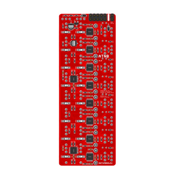
01. INSTALL ATION When you turn ATN8 around, you should see the module as it is on the left illustration. Plug in the power cable to the TL074 power cable header pins, but BE CAREFUL with the orien- TL074 tation of the cable! The RED STRIPE should be towards the... -
Page 5: Jack Lights
02. JACK LIGHTS On the back there is a jumper for enabling the jack lights. Note that by enabling them the module draws additional TL074 current from the +12V rail. TL074 TL074 Jack lights jumper TL074 TL074 TL074 TL074 TL074... -
Page 6: Front
03. FRONT 1 Voltage switch for channels 5-8 2 Voltage switch for channels 1-4 3 Status LED for the channel 4 Unipolar/Bipolar switch for each channel 5 Attenuator for each channel 6 Input for each channel (+/-12V) 7 Output for each channel (+/-12V) -
Page 7: Overview
04. OVERVIE W ATN8 is an eight channel attenuator with inverting, mix- ing and offset capabilities. The 8 channels are laid out horizontally, each with a switch to change between uni- polar and bipolar modes, a status LED that reflects what’s happening on the output (green is positive voltage, red is negative), an input and an output jack. -
Page 8: Attenuators
05. AT TENUATORS Each channel is equipped with a switch to change how the UNIPOLAR potentiometer functions. In unipolar mode the potenti- BIPOLAR ometer goes the full range, fully counter-clockwise the output is 0V, fully clockwise it matches the input level. In bipolar mode 0V is at 12 o’clock, turning the potenti- ometer clockwise it increases the output level. -
Page 9: Mixing
06. MIXING Mixing is achieved by normalization, meaning that if you INPUT 1 leave the output jacks unplugged, the last output jack that you patch in will contain the mix of all the previous INPUT 2 channels (level set by the attenuators). A patch cable in the output jack breaks the normalization and on the next INPUT 3 MIX OF CH 1-3... -
Page 10: Offset
07. OFFSE T If there is no cable patched in an input, the channel uses INPUT 1 a preset voltage, changed by the top switches. There are INPUT 1 WITH two options: OFFSET . is 5V GROUP A .. is 10V The 8 channels are split into two groups for the preset voltage, each set independently by their corresponding switches. - Page 11 ATN8 is designed by David Szebenyi under Antumbra. www.antumbra.eu Manual by David Szebenyi (www.aman.hu) 2021 • All rights reserved!


Need help?
Do you have a question about the ATN8 and is the answer not in the manual?
Questions and answers