Table of Contents
Advertisement
Quick Links
TOOLS REQUIRED FOR ASSEMBLY
Electric Hand Drill, Phillips Head Bit, 3/8" Magnetic Hex
Driver Bit, Socket Set and Ratchet.
BEFORE ASSEMBLING THE WORKBENCH
Read through the assembly instructions to familiarize your-
self with the order in which the parts are assembled.
We suggest that you clear & vacuum the area where the
bench is to be assembled.
It is important that the bench is assembled in the same
sequence as instructed.
HARDWARE
All assembly hardware is provided.
Flip the desks top upside down on a blanket or other clean
surface to avoid scratching the top.
Attach the legs to the top using the (4) 1/4-20 x 2-1/2" hex
head bolts by threading into the pre-installed nuts in the
top.
1/4-20 x 2-1/2"
Hex Head Bolt
3985 S. Fletcher Road ∙ Chelsea, MI 48118
(800) 396-4642 ∙ Fax (734) 428-7672
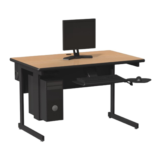
PCL Workstation
www.greenemfg.com
Advertisement
Table of Contents

Related Manuals for GMI PCL


Summary of Contents for GMI PCL
- Page 1 3985 S. Fletcher Road ∙ Chelsea, MI 48118 (800) 396-4642 ∙ Fax (734) 428-7672 www.greenemfg.com PCL Workstation TOOLS REQUIRED FOR ASSEMBLY Electric Hand Drill, Phillips Head Bit, 3/8” Magnetic Hex Driver Bit, Socket Set and Ratchet. BEFORE ASSEMBLING THE WORKBENCH Read through the assembly instructions to familiarize your- self with the order in which the parts are assembled.
- Page 2 3985 S. Fletcher Road ∙ Chelsea, MI 48118 (800) 396-4642 ∙ Fax (734) 428-7672 www.greenemfg.com Once legs are attached position the counter top support brace between the legs towards the front edge of the desk. Attach the brace to the legs using (4) 1/4-20 x 3/4” flange head bolts by threading into the pre-installed nuts in the leg.
- Page 3 3985 S. Fletcher Road ∙ Chelsea, MI 48118 (800) 396-4642 ∙ Fax (734) 428-7672 www.greenemfg.com Skip this step if no wire management tray was ordered. Set the wire tray in place on the top, do not attach the tray yet. Insert the modesty panel between the desks legs.
- Page 4 3985 S. Fletcher Road ∙ Chelsea, MI 48118 (800) 396-4642 ∙ Fax (734) 428-7672 www.greenemfg.com Once the modesty panel is secure, finish attaching the wire tray (if ordered). Use 5/8” spax head screws and mount to the underside of the top through the mounting holes at the back edge of the desk.
Need help?
Do you have a question about the PCL and is the answer not in the manual?
Questions and answers