Table of Contents
Advertisement
Quick Links
Advertisement
Table of Contents

Related Manuals for PDK PDR1000


Summary of Contents for PDK PDR1000
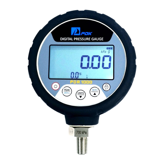
- Page 1 PDR1000 Digital Pressure Gauge Users Manual...
-
Page 2: Table Of Contents
Table of Contents 1. General Introduction ……………………………………………………………………………………… 2. Abbreviations & Initials ………………………………………………………………………………… 3. Introduction ………………………………………………………………………………………………… 3.1 Specification …………………………………………………………………………………… 3.2 Front / Back panel …………………………………………………………………………… 4. Operation ………………………………………………………………………………………………… 4.1 Key Operation …………………………………………………………………………………… 4.1.1 Power On …………………………………………………………………………… 4.1.2 PEAK …………………………………………………………………………………… 4.1.3 UNIT ……………………………………………………………………………………... -
Page 3: General Introduction
This manual is intended to provide the user with the basic information necessary to operate a PDR1000 (Digital Pressure Gauge). It also includes a great deal of additional information provided to allow you to optimize PDR1000 use and take full advantage of its many features and functions. Manual Conventions “Caution”... -
Page 4: Abbreviations & Initials
PDK produced PDR1000 with PDK’s unique pressure calibration and production technology that has best performance in its class. PDR1000 is digital pressure gauge for precise pressure measurement and test with Built-in various features. Simply use buttons on front panel to operate and select various functions and external power input section, analog output port (1 to 5 VDC), and communication port (RS232) and batteries change socket on rear panel. -
Page 5: Specification
3.1 Specification Pressure Range -100 kPa to 150 MPa 0 to 250 MPa 0 to 500 MPa Gauge : ±0.025% F.S ±0.05% F.S ±0.1% F.S Absolute / Compound : ±0.05% F.S Accuracy ** Included Nonlinearity, Hysteresis, Repeatability, errors for -10 ~ 50 ℃ Temperature range Over Pressure limit 150 % of full scale Bust Pressure... -
Page 6: Front / Back Panel
Peak shows maximum and minimum pressure value. Menu makes selection and set for Alarm, Switch, CAL, Baud Rate, Auto Power Off, and Data Logger. Saved peak value will be clear when PDR1000 turns off. 3.2.3 UNITS / Analog out / Down Key Change the pressure units and On/Off for Analog output. - Page 7 3.2.5 Back Light / Enter Key Backlight On/Off Use Enter key to set up the Menu. [ D-Sub 9 Pin Map ] Figure 2. RS-232 Port Pin No Description Note RS232 Analog Output Analog Out+ Ext. Switch In Alarm Out Ext.
-
Page 8: Operation
Screen at no pressurize or Zero set. 4.1.2 PEAK / MENU PEAK : Peak shows maximum and minimum pressurized value on PDR1000. MENU Push PEAK/MENU key indicates Hi for maximum pressurized value. Push PEAK/MENU key again, indicates Lo for minimum pressurized value. -
Page 9: Back Light
Absolute mode, make vacuum state (under 1 × 10 torr) then ZERO key for 2 seconds to zeros the display. Zero key can clear the Peak Hi Low values when Peak mode. Also it can select the set up when Pressure Switch mode. 4.1.5 Back Light / Enter : Push to turn on the backlight. - Page 10 Alarm Alarm Low value setup screen on above. Digits on above screen is percentage value of PDR1000 Full Scale. Push ZERO key and UNITS key to change percentage value. After push Enter key to save Alarm Low value, Alarm Hi value setup screen shows with blink.
-
Page 11: Pressure Switch Test
Alarm Alarm Electric Contact Alarm Signal setup screen on above. Push ZERO key to select Normal Close or Normal Open status set. Push Enter key to save Electric Contact Alarm Signal setup. < Electric Contact Alarm Signal operation mode > - Pressure + Pressure <... - Page 12 < Operation Mode > 1) Operation for External Pressure Switch Off to On Pressure Switch function “ON” screen on above. If PDR1000 received external electric contact signal (Switch turns Off to On) Hold Switch icon will change from open to close ( ) then pressure value will be hold status with “Hold”...
- Page 13 If PDR1000 received external electric contact signal (Switch turns On to Off), Switch icon will change from close to open ( ) then pressure value will be hold status with “Hold” icon blinking. Hold Even supply pressure changed, Pressure value will keep hold until push ZERO key.
-
Page 14: Calibration
< Normal Open type > - Pressure + Pressure PSV : Pressure safety Valve Hys : Hysteresis Value (Caution) Do not pressurize quickly during Pressure Switch Test. 4.2.3 Calibration PEAK MENU Figure 5. Calibration flowchart Calibration function can adjust Zero and Full Scale value. Zero Adjustment –... -
Page 15: Baud Rate
display shows current adjusted pressure value. Full Scale adjustment should be adjusted within ±10% of full scale value and displayed full scale value adjust with Pressure controller/calibrator or Piston gauge. 4.2.4 Baud Rate ZERO PEAK MENU Figure 6. Baud Rate setup flowchart This function can set Baud Rate for RS232 Communication. -
Page 16: Rs232 Communication
4.2.5 RS232 Communication <RS232 Communication Set> Baud Rate : 19200 Data Bit Length : 8 bit Stop Bit : 1 bit Parity : None Data flow control : N/A Data Code : ASCII code <Description> BL : Blank C1 : Command1 C2 : Command2 LF : Line Feed CR : Carriage Return... - Page 17 4. Continuous sample Pressure value, Temperature value 5 Byte 1 Byte 3 Byte 1 Byte 6 Byte 1 Byte [001] MDAUTO [001] P = -0.00136, T = 24.95 [001] P = -0.00136, T = 24.95 < Response Example > [001] P = -0.00132, T = 24.95 [001] P = -0.00126, T = 24.95 5.
-
Page 18: Auto Power Off
4.2.6 Auto Power Off ZERO PEAK MENU Figure 7. Auto Power Off setup flowchart Auto Power Off function can set Auto Off. This function can use after Auto Power Off function on. Choose one of 5 min, 10 min, 20 min, and 30 minutes. Push PEAK/MENU key for 2 seconds to select Menu function then push PEAK/MENU key to choose Auto Power Off function. -
Page 19: Data Logger
4.2.7 Data Logger ZERO Figure 8. Data logger setup flowchart Push PEAK/MENU key for 2 seconds to select Menu function. Push PEAK/MENU key to select Data Logger function. Push ZERO key to set Data Logger function. Push ENTER key to save Data Logger status. Push ENTER key to go to next Menu when Data Logger off, push ENTER key to set Data Logger function save and time mode when Data Logger On. - Page 20 After Menu sets then use Logger function, push ENTER key to 2 seconds then display shows “Log” with blinking. At this moment, unable to use RS232 Communication because PDR1000 is saving pressure value at the same time. Push ENTER key for 2 seconds to stop Data Logger function.
-
Page 21: Storage Data Clear
4.2.8 Storage Data Clear Push PEAK/MENU key for 2 seconds to select Menu. Push PEAK/MENU key to select Data Clear function. Push ZERO to Data clear or not. This function is erase saved data on EPROM. 4.2.8 End This function is save all of Menu. This is last function to activate and store for each configured setting. -
Page 22: Maintenance Adjustments And Calibration
5. Maintenance Adjustments and Calibration 5.1 Zero Adjustment Using PDR1000 for a long time, it occurs Zero point change because of yearly variation for pressure sensor and PCB components or other environmental condition. If user wants to set Zero, use Calibration Zero function on CAL Function. -
Page 23: Troubleshooting
PDK does not recommend to user open the case to solve the PDR1000 problem. PDK does not guarantee when PDR1000 got damage with user open the case in PDR1000. PDK recommends contacting/send PDR1000 to PDK for suitable and stable troubleshooting. -
Page 24: Appendix
7. Appendix 7.1 Warranty Statement PDR1000 warranty period of quality is 3 years. PDK guarantee all of case of failure symptom except user’s fault within 3 years. Even when warranty is expired, PDK will help our customer with minimum repair fee. -
Page 25: Table Of Pressure Unit Conversion
7.3 Table of pressure unit conversion unit kgf/cm mmHg 0.101 325 1 013.250 1.013 250 14.695 94 1.0332 27 760.000 0 10 332.27 9.869 239 10 000.00 10.000 00 145.037 7 10.197 16 7 500.622 101 971.6 0.000 987 0.000 100 0.0010 00 0.014 504 0.001 020...
Need help?
Do you have a question about the PDR1000 and is the answer not in the manual?
Questions and answers