Table of Contents
Advertisement
Quick Links
Advertisement
Table of Contents

Subscribe to Our Youtube Channel
Related Manuals for SEPTENTRIO AsteRx-i S


Summary of Contents for SEPTENTRIO AsteRx-i S
- Page 1 AsteRx-i S and AsteRx-i V Product Group Hardware Manual Version 1.0.2...
- Page 2 AsteRx-i S and AsteRx-i V Product Group Hardware Manual Version 1.0.2 September 14, 2018 © Copyright 2000-2018 Septentrio nv/sa. All rights reserved. Septentrio Greenhill Campus, Interleuvenlaan 15i 3001 Leuven, Belgium http://www.septentrio.com support@septentrio.com Phone: +32 16 300 800 Fax: +32 16 221 640...
-
Page 3: Table Of Contents
1 Table of contents TABLE OF CONTENTS ....................3 ASTERX-I OEM GNSS MODULE ..................8 Mounting ........................9 Environmental ......................9 Power and Power Consumption ................9 RF Interface ......................10 2.4.1 Electrical Specifications .................... 10 2.4.2 System Noise Figure and C/N0 ................10 I/O Connectors ....................... - Page 4 Power Consumption ....................24 Connector ....................... 24 Open-Ended Cable ....................25 ASTERX-I UAS (PRELIMINARY) .................. 26 Connectors ......................27 Power Supply Options ................... 28 LEDs ......................... 28 Temperature Range ....................28 Schematics ......................28 UAS to IMU Cables ....................31 DEVELOPMENT KIT ......................
- Page 5 ROHS/WEEE NOTICE AsteRx-i complies with European Union (EU) Directive 2002/95/EC on the restriction of the use of certain hazardous substances in electrical and electronic equipment (RoHS Directive). AsteRx-i complies with the European Union (EU) Directive 2002/96/EC on waste electrical and electronic equipment (WEEE). The purpose of this Directive is the prevention of waste electrical and electronic equipment (WEEE), and in addition, the reuse, recycling and other forms of recovery of such wastes so as to reduce the disposal of waste.
- Page 6 Statement 0001/WARNING: The power supply provided by Septentrio (if any) should not be replaced by another. If you are using the receiver with your own power supply, it must have a double isolated construction and must match the specifications of the provided power supply.
- Page 7 WARNING: Handling of ESD Sensitive Devices Electrostatic discharge is a sudden flow of current from one object to another either object or to ground. Electrostatic charges can accumulate on common items such as polystyrene drinking cups, cellophane tape, synthetic clothing, untreated foam packaging material, and untreated plastic bags and work folders, to name but a few.
-
Page 8: Asterx-I Oem Gnss Module
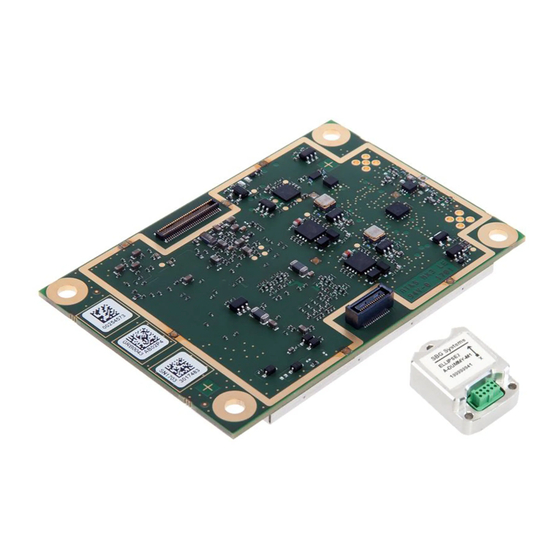
AsteRx-i OEM GNSS Module 2 AsteRx-i OEM GNSS Module Pin#1 view from above, I/O connectors on the bottom side Pin#1 All dimensions in millimeters. Weight = 28 g RF connectors (u.FL type) are mounted on top side of the PCB. The 30- and 60-pin Hirose I/O connectors are mounted on the bottom side. -
Page 9: Mounting
AsteRx-i OEM GNSS Module 2.1 Mounting The four mounting holes are compatible with M3 screws. Use M3 3.5mm spacers. An example of applicable SMD spacer is THF-1.6-3.5-M3 from MAC8. All mounting holes are grounded, and should preferably be connected to ground on the host PCB. -
Page 10: Rf Interface
AsteRx-i OEM GNSS Module 2.4 RF Interface The main antenna must be connected to the ANTA u.FL and the auxiliary antenna must be connected to the ANTB u.FL connector. 2.4.1 Electrical Specifications Antenna supply voltage 3-5.5V DC, set via pin#18 of the 30-pin connector. The DC voltage is applied to both antenna connectors. - Page 11 AsteRx-i OEM GNSS Module For example, with a 2.5-dB antenna LNA noise figure, 30-dB antenna LNA gain and 15-dB cable loss, Gpreamp = 30dB-15dB = 15dB. In this case, the system noise figure is: NFsys = 10.log 2.5/10 + (10 10/10 -1)/10 15/10...
-
Page 12: I/O Connectors
AsteRx-i OEM GNSS Module 2.5 I/O Connectors 60 pin 30 pin The main connector is the 30-pin connector. That connector must always be connected. The 60-pin connector provides additional signals (IO enable, serial CTS/RTS lines, GPIOs, Ethernet, 10-MHz reference input, etc). That connector can be ignored and left unconnected if these signals are not needed. -
Page 13: 30-Pin Connector
AsteRx-i OEM GNSS Module 2.5.1 30-pin Connector Connector type: Hirose 30 pins DF40HC (3.5)-30DS-0.4V(51) Mating connector: Hirose DF40C-30DP-0.4V(51) See the pin numbering convention in the above picture. Pin# Name Type Level Description Comment 3.3V Main power supply input Both Vin pins (pin#1 and pin#2) must +/-5% be tied together. -
Page 14: 60-Pin Connector
AsteRx-i OEM GNSS Module 2.5.2 60-pin connector Connector type: Hirose DF40C-60DP-04V(51) Mating connector: Hirose DF40HC(3.5)-60DS-0.4V(51) See the pin numbering convention in the above picture. Pin# Name Type Level Description Comment Reserved Reserved Reserved Reserved LVTTL General purpose output. GP1 in setGPIOFunctionality command. See section 2.7 RTS2 LVTTL... - Page 15 AsteRx-i OEM GNSS Module Pin# Name Type Level Description Comment Reserved Ground Reserved Ground Reserved CTS2 I, K LVTTL Serial COM 2 CTS line. Must be driven low when ready to receive data from the AsteRx-i OEM. CTS3 I, K LVTTL Serial COM 3 CTS line.
-
Page 16: Event Inputs
AsteRx-i OEM GNSS Module 2.6 Event Inputs The receiver features two event inputs (EventA on the 30-pin connector, and EventB on the 60-pin connector), which can be used to time tag external events. Use the setEventParameters command to configure these pins (e.g. to set the polarity). Note that this feature requires the TimedEvent (event marker) permission to be enabled in the receiver. -
Page 17: Usb Interface
AsteRx-i OEM GNSS Module See instructions in the Reference Guide for details on how to configure SD card logging. The receiver is compatible with SD cards of up to 32GB. The file system is FAT32. Shortly driving the button pin (pin#25 of 30-pin connector) low toggles logging on and off. Driving the button pin low for at least 5 seconds unmounts the SD card if it was mounted, or mounts it if it was unmounted. -
Page 18: Ethernet
AsteRx-i OEM GNSS Module Note that the USB VBUS pin cannot be used to supply power to the receiver. 2.11 Ethernet The receiver supports full duplex 10/100 Base-T Ethernet communication. The Ethernet PHY and magnetics are to be implemented on the host board. Connection with the PHY is through the RMII interface available on the 60-pin connector. - Page 19 AsteRx-i OEM GNSS Module...
-
Page 20: Sbg Ellipse2 Micro
SBG Ellipse2 Micro 3 SBG Ellipse2 Micro 3.1 Dimensions All dimensions in mm. The IMU reference point is marked by the symbol. -
Page 21: Environmental
3.5 Open-Ended Cable Septentrio’s CBL_AxiS_OEM_IMU cable (part# 215684) can be used to connect the IMU to the AsteRx-i S OEM. Twisted pairs are used when applicable to prevent cross-talk between digital signals. The wiring diagram and the wire colors are indicated below. - Page 22 SBG Ellipse2 Micro It is recommended to connect the IMU to COM3 of the AsteRx-i OEM module (which is the default IMU port). Conversion from RS-232 to TTL level is needed. If using another port than COM3, it must be specified to the firmware with the setIMUInput command. The SYNC A pin of the IMU must be connected to the PPSout pin of the AsteRx-i OEM.
-
Page 23: Vn-100 Rugged
VN-100 Rugged 4 VN-100 Rugged 4.1 Dimensions All dimensions in inches [mm]. The IMU reference point is marked by the symbol. -
Page 24: Environmental
VN-100 Rugged 4.2 Environmental Operational: -20 to +65 °C Storage: -40 to +85 °C 4.3 Power Consumption The IMU consumes 220mW. 4.4 Connector The main connector used on the VN-100 Rugged is a 10-pin Harwin M80-5001042. The mating connector is a Harwin M80-4861005. The input voltage range (VCC pin) is from 4.5V to 5.5V. -
Page 25: Open-Ended Cable
VN-100 Rugged 4.5 Open-Ended Cable Septentrio’s CBL_AxiV_OEM_IMU cable (part# 215686) can be used to connect the VN-100 IMU to the AsteRx-i V OEM module. Twisted pairs are used when applicable to prevent cross-talk between digital signals. The wiring diagram and the wire colors are indicated below. -
Page 26: Asterx-I Uas (Preliminary)
This chapter provides information on the UAS board only. Refer to chapter 2 for the specifications of the AsteRx-i OEM module. The version of the UAS board described here is preliminary and subject to change. It should not be be used in final designs. Contact Septentrio Support for details (support@septentrio.com). Shutter... -
Page 27: Connectors
AsteRx-i UAS (PRELIMINARY) 5.1 Connectors Type Description Usage Example 30-pin DF40C Connector to the AsteRx-i OEM board Micro B USB USB interface to AsteRx-i OEM Connect to laptop or PC to power the system and control the AsteRx-i. DF13-6P-1.25DSA COM1 TTL UART from AsteRx-i OEM. Pin#1 is a 5V power input DF13-6P-1.25DSA COM2 TTL UART from AsteRx-i OEM. -
Page 28: Power Supply Options
AsteRx-i UAS (PRELIMINARY) Note that the 60-pin connector of the AsteRx-i OEM is not used by the UAS board. Refer to the board schematics in section 5.5 and to the picture on page 20 for the pinout of each connector. 5.2 Power Supply Options When an USB cable is connected, the UAS board is powered from the computer through the USB connector (J2). - Page 29 AsteRx-i UAS (PRELIMINARY) Note that the connection to the SD-card differs from the recommended circuit in section 2.9. The UAS board connects the SD-card DAT3 pin to pin#24 of the 30-pin connector of the AsteRx-i OEM. This connection is there to make the interface board compatible with the legacy AsteRx-m receiver.
- Page 30 AsteRx-i UAS (PRELIMINARY) See note above...
-
Page 31: Uas To Imu Cables
AsteRx-i UAS (PRELIMINARY) 5.6 UAS to IMU Cables Connecting the UAS board to the IMU can be done using one of the following cables supplied by Septentrio: CBL_AxiS_UAS_IMU (part#215691) to an SBG Ellipse2 Micro. • CBL_AxiV_UAS_IMU (part#215686) to a VN-100 Rugged. -
Page 32: Development Kit
Development Kit Development Kit POWER PPS/EVENTS 1&2 USB Dev USB Host 3&4 REF IN Additionally to the UAS interface board, a Development Kit is available to ease the development process for new integrations. 5.7 Powering the DevKit There are two ways to power the DevKit: 1. -
Page 33: Antenna Connectors
Development Kit To measure the power consumption of the AsteRx-i OEM module (excluding the contribution from the DevKit itself, the IMU and the antenna), remove the jumper on J200 and connect the two pins to the probes of a multimeter in current-sensing mode. Measure the current flowing between the two pins and multiply it by 3.3V to obtain the power consumption. -
Page 34: Leds
Development Kit 5.9 LEDs - POWER - GPLED - LOGLED The POWER LED lights when the DevKit is powered. The GPLED and LOGLED are connected to the homonymous pins of the 30-pin connector of the AsteRx-i board. See section 2.5.1 for the pinout, and Appendix A for a description of the LED behavior. -
Page 35: Pps Out And Event Inputs
Development Kit COM1 COM2 COM3 COM4 5.11 PPS Out and Event Inputs PPSOUT EVENTB EVENTA The PPSout pin of header J500 is directly connected to the PPSOut pin of the AsteRx-i OEM (see section 2.5.1). The PPS level is 3.3V. The EVENTA and EVENTB pins of J500 are connected to the EventA and EventB pins of the AsteRx-i through a buffer. -
Page 36: Usb Dev
Development Kit 5.13 USB Dev That connector can be attached to a PC to power the DevKit and to communicate with the receiver over its USB port. 5.14 USB Host Reserved. 5.15 REF IN Reserved. 5.16 Buttons nRST LOGGING Pressing the nRST button drives the nRST pin of the AsteRx-i OEM low, which resets the receiver. -
Page 37: Connection With Imu
Development Kit 5.18 Connection with IMU Septentrio’s open ended IMU cables (see sections 3.5 and 4.5) can be used to connect the DevKit to the IMU. The following connections are recommended: PPS out: to IMU SYNC 5V out: to IMU PWR... -
Page 38: Appendix Aled Status Indicators
LED Status Indicators Appendix A LED Status Indicators The LED pins of the OEM module can be used to monitor the receiver status. They can be used to drive external LEDs (max drive current 10mA). It is assumed that the LED lights when the electrical level of the corresponding pin is high. - Page 39 LED Status Indicators The LOGLED reports the SD card mount status and logging activity. LED Behaviour LOGLED LED is off when the SD card is not present or not mounted. LED is on when the SD card is present and mounted. Short blinks indicate logging activity.
-
Page 40: Appendix Bemc Considerations
EMC Considerations Appendix B EMC Considerations In applications in which the electronics are collocated with the GNSS antenna, cross-talk could be a major concern. GNSS signals are very weak and easily interfered by radiated harmonics of digital signals. The most useful indicator of the signal reception quality is the C/N0 of the satellites in view. - Page 41 EMC Considerations An example of interference is shown below. This particular interference at about 1598 MHz falls in the GLONASS L1 band and slightly degrades the L1 C/N0 of some GLONASS satellites. Try to keep personal computers and other equipment more than 2 meters away from the antenna while assessing electromagnetic compatibility of the integration.
- Page 42 EMC Considerations Intermittent interference (µs-scale) has little impact if its duty cycle is below 10%. For example, these short pulses from a digital circuit close to the antenna are essentially harmless. If interference is detected, look for the root cause by switching off devices. Typical sources of interference are: Unshielded flat cables carrying digital signals or power signals towards digital •...
Need help?
Do you have a question about the AsteRx-i S and is the answer not in the manual?
Questions and answers