Table of Contents
Advertisement
Quick Links
Advertisement
Table of Contents

Subscribe to Our Youtube Channel
Related Manuals for MEI Geo Gravity


Summary of Contents for MEI Geo Gravity
- Page 1 Operation & Maintenance Manual MEI Inc. 2008 254055001 Rev. G3...
-
Page 2: Table Of Contents
Table Of Contents TECHNICAL SPECIFICATION ..............................3 ESD P ..................................3 RECAUTIONS PRODUCT DETAIL..................................4 ....................................5 LEANING ..................................5 SITE CLEANING .................................5 HOROUGH LEANING .....................................5 AINTENANCE INTERFACE DESCRIPTIONS...............................6 :..........................6 IELD ONFIGURABLE NTERFACE ETTINGS ..............................6 NTERFACE WITCHING ..........................6 ESET CC OMMUNICATION ARAMETERS : ..................................7 ULSE NTERFACE :.................................8 ARALLEL... -
Page 3: Technical Specification
Technical Specification The Geo line of bill acceptors accepts bank notes through 85 mm in width. The Geo SL comes pre- programmed, per customer specification, from the factory or can be reconfigured by customers utilizing the gFlash program for PC’s. Software updates can also be uploaded into the Geo via a PC enabled with the gFlash program. -
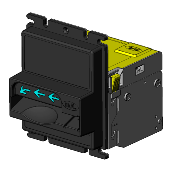
Page 4: Product Detail
Product detail 1. Bill Entry Area 3. Data Port 5. Upper section release button 2. Mounting Bracket/BEG 4. I/O Port... -
Page 5: Cleaning
Refer to the top mounted diagnostic LED on the Geo. If the LED is flashing, refer to the diagnostic card on the top of the unit to detail the possible problem. If you cannot rectify a problem on site, please contact your local MEI authorized service center or MEI. -
Page 6: Interface Descriptions
Interface Descriptions Field Configurable Interface Settings: Interface Switching Mode This feature is enabled only when the GeoSL is set to one of the following interfaces: • Pulse • Parallel • Parallel binary • ccTalk (ccTalk requires that a ccTalk interface module (VT-PCBA12) be installed in the GeoSL) 1. -
Page 7: Pulse Interface
Pulse Interface: The Pulse Interface provides a corresponding signal on the output line that designates the particular note validated. IF Cable: VA-WIRA06 Input Power: 12 VDC Connector Viewed Facing Acceptor Pin 1: +12 VDC Pin 2: Ground/Earth (power) Pin 4: Credit Pulse Output (open collector to Ground/Earth) Pin 5: Alarm Output (open collector to Ground/Earth) Pin 6: Enable Input (tied to Ground/Earth to enable acceptor) Pin 12: Busy (open collector to Ground/Earth. -
Page 8: Parallel Interface
Parallel Interface: The Parallel interface provides specific output lines for designating which note has been validated. This interface also provides for escrow and alarm functions. Outputs are open collector and can sink up to 100mA at up to 24VDC. Inputs are TTL Default setting for the outputs is active low, it is possible to set them to operate active high with the mFlash configuration software. -
Page 9: Escrow
Escrow: This mode allows 'on the fly' enabling and disabling of each denomination accepted by the bill acceptor. The enable and escrow lines are used in combination to allow this. The procedure for accept and return is as follows; 1. Enable line and Escrow line are held low (0V) by the host machine. On insertion of a valid bill, the bill acceptor outputs the relevant pulse and holds the bill. -
Page 10: Parallel Binary Interface
Parallel Binary Interface: This interface utilizes the first four of the Parallel outputs. Instead of a single pulse on each line to denote a particular denomination as in the Parallel interface, the Parallel Binary credit information is sent as a low going output pulse (100mS) which is sent simultaneously on the required lines. -
Page 11: Cctalk Interface
ccTalk Interface: cctalk b96.p0.v12.a12.d0.c5.m0.x16.e1.i0.r14 9600 baud rate Open Collector interface Nominal 12V supply Serial Data pull-up voltage 12V (determined by external pull-up voltage) Supply sink Connector type 5 (IDC-10) Slave device only CRC-CCITT checksum Encryption Type 1 Minor release 0 Major release 4 IF Cable: 252070058C Connector Viewed Facing Acceptor... -
Page 12: True" Rs232
"True" RS232 The ‘True’ RS232 interface provides for comms. between a Host (PC) and Slave (acceptor). This interface operates at ‘True’ RS232 levels and allows direct connection between the acceptor and PC comm. port without the need for special interface harness/loom. 9600 bps, 1 start bit, 1 stop bit, 7 data bit format. -
Page 13: Ttl Rs232
TTL RS232 The TTL RS232 interface operates at TTL levels, 9600 bps, 1 start bit, 1 stop bit and 7 data bits. IF Cable: VA-WIRA06 Input Voltage: +12 VDC Pin1: +12 VDC Pin 2: Ground/Earth (power) Pin14: TTL RXD (receive data to acceptor) Pin 15: Common Pin 16: TTL TXD (transmit data from acceptor) For complete technical detail on the RS232 interface, refer to manual VTIRS-x... -
Page 14: Serial Interface
Serial Interface: The Serial interface is a MEI compatible, bi-directional interface. It operates at 600 bps, 1 start bit, 1 stop bit and 8 data bits. I/F Cable: VA-WIRA06 Input Voltage: 12 VDC Viewing Towards Acceptor Pin 1: +12 VDC Pin 2: Ground/Earth (power) Pin 5: Alarm Output (open collector to Ground/Earth. -
Page 15: Dimensional Detail
Dimensional Detail Glass mount plastic Bezel Entry Guide... -
Page 16: Standard Mount Plastic Bezel Entry Guide
Standard Mount Plastic Bezel Entry Guide... -
Page 17: Model Number Detail
Model Number Detail SL - S - A - XXX Series Model Country ISO code Stackerless S=Standard A=Standard BEG USD=United States B= Universal BEG EUR=Europe R=RS232 C=CC Talk Diagnostic Codes The diagnostic codes for the Geo are related to the diagnostic LED found on the top of the Geo bill acceptor. -
Page 18: Programming
Programming The Diagnostic Button on top of the GeoSL is capable of several functions: • Enable a note in the currently installed dataset • Disable a note in the currently installed dataset • Field calibration • Interface Switching (see page 7) Enable a note Press the Diagnostic Button once, the Diagnostic LED will turn green and flash quickly.
Need help?
Do you have a question about the Geo Gravity and is the answer not in the manual?
Questions and answers