Advertisement
Advertisement
Table of Contents

Subscribe to Our Youtube Channel
Related Manuals for NEW ENERGY NERS-G50Y-B1


Summary of Contents for NEW ENERGY NERS-G50Y-B1
- Page 1 SWIMMING POOL HEAT PUMP UNIT Installation & Instruction Manual Please read this manual carefully before using and keep it in a safe place.
-
Page 2: Table Of Contents
DC INVERTER SWIMMING POOL HEAT PUMP SERIES USER MANUAL Please read this manual carefully before using and keep it in a safe place. Contents I. Unit Parameters.............................. 1 II. System Specification............................. 4 1. Specification............................4 2. Unit Dimensions............................. 8 3. Explosion View............................. 10 III. -
Page 3: Unit Parameters
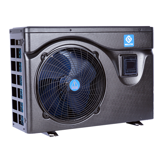
I. Unit Parameters 1. Appearance 2. Statement To keep users under safe working condition and property safety, please follow the instructions below. Wrong operation may result in injury or damage; Please install the unit in compliance with local laws, regulations and standards; ... - Page 4 ⚠ Warning Make sure that the unit is installed safely and reliably. If the unit is not secure or not installed, it may cause damage. The minimum support weight required for installation is 21g/mm If the unit was installed in a closed area or limited space, please consider the size of room and ...
- Page 5 Don't touch or operate the unit when your hands are wet. It may cause fire or electric shock. Don't place heaters or other electrical appliances near the power wire.It may cause fire or electric shock. The water must not be poured directly from the unit. Do not let water to permeate into the ...
-
Page 6: System Specification
If power wire is damaged, it must be replaced by a professional technician to avoid danger. II. System Specification 1. Specification Model NERS-G50Y-B1 NERS-G70Y-B1 NERS-G90Y-B1 Air temperature: 26ºC, inlet / outlet water temperature: 26ºC/28ºC, Humidity 80% Heating capacity(kW)... - Page 7 Air temperature: 35ºC, inlet / outlet water temperature: 28ºC/26ºC Cooling capacity(kW) 1.5~3.1 1.7~3.8 1.8~4.9 Power input(kW) 0.208~0.704 0.229~0.854 0.242~1.101 EER(kW) 4.4~7.2 4.45~7.42 4.45~7.44 Cooling capacity(kW) Boost mode 4.45 4.45 Cooling capacity(kW) 2.92 Smart mode 5.64 5.63 5.63 Cooling capacity(kW) 2.18 Silent mode 6.97 6.97...
- Page 8 Noise level dB(A) 20~45 20~46 21~46 The technical specification of our heat pumps is provided for information purpose only. We reserve the right to make change without notice in advance. 1. Ambient temperature 2. Initial water temperature 3. Noise at 1m, 4m and 10m comply with Directives EN ISO 3741 and EN ISO 354 4.
- Page 9 Air temperature: 35ºC, inlet / outlet water temperature: 28ºC/26ºC Cooling capacity(kW) 2.42~6.3 3.35~7.95 4.11~9.82 Power input(kW) 0.327~1.438 0.452~1.811 0.556~2.278 EER(kW) 4.38~7.4 4.39~7.41 4.31~7.39 Cooling capacity(kW) 7.95 9.82 Boost mode 4.38 4.39 4.31 Cooling capacity(kW) 4.89 6.45 7.77 Smart mode 5.42 5.45 5.36 Cooling capacity(kW)...
-
Page 10: Unit Dimensions
3. Noise at 1 m, at 4 m and at 10 m in accordance with Directives EN ISO 3741 and EN ISO 354 4. Calculate according to an in-ground private swimming pool covered with bubble 2. Unit Dimensions Model: NERS-G50Y-B1 , NERS-G70Y-B1, NERS-G90Y-B1... - Page 11 Model: NERS-G110Y-B1, NERS-G150Y-B1, NERS-G180Y-B1...
-
Page 12: Explosion View
3. Explosion View Front plate Framework Right plate Controller box Compressor Water flow switch Fan motor cover Middle plate Evaporator Four way valve Protection net Motor Throttle valve Inverter PC board Motor support Titanium heat exchanger Electrical box Left plate Handle Top cover Chassis component... -
Page 13: Installation Instructions
III. Installation Instructions WARNING: Installation must be carried out by a qualified engineer. This section is provided for information purpose only and must be checked and adapted if necessary according to actual installation condition. 1. Pre-Requirements Needed equipment for installation of heat pump: Suitable power supply cable for unit’s power. - Page 14 Anything could not be placed within 1m in front of heat pump. Leave 50cm of empty space around the sides and rear of heat pump. Do not put any stuff on or in front of heat pump! 3. Installation Layout The heat pump is connected to a filtration circuit with a by-pass valve.
- Page 15 4. Parallel Installation for 2 Units 5. Electrical Connection Power Supply Wires Size Power Supply Wires Model Electricity Supply Cable Diameter Specification NERS-G50Y-B1 3×2.5mm AWG 14 NERS-G70Y-B1 3×2.5mm AWG 14 NERS-G90Y-B1 3×2.5mm AWG 14 220-240V/1N~50Hz NERS-G110Y-B1 3×2.5mm AWG 14 NERS-G150Y-B1 3×2.5mm...
- Page 16 NERS-G50Y-B1,NERS-G70Y-B1,NERS-G90Y-B1,NERS-G110Y-B1...
- Page 17 NERS-G150Y-B1,NERS-G180Y-B1...
-
Page 18: Running Test
IV. Running Test 1. Inspection Before Running Test a. Running test can begin after completing all installation; b. Before running test, confirm below items and write √ in block; Correct unit installation □ Power supply voltage is the same as unit rated voltage □ ... - Page 19 Basic Icons 1. When in heating mode, icon shows ; 2. When in Cooling mode, icon shows ; 3. When in defrosting mode, twinkling icon shows 。 When off status, the display shows the current time Key Operating Instruction ...
- Page 20 Timer Cancel When the “Timer on”and “Timer off” is the same, timer will be canceled. At the interface of setting “Timer on” or “Timer off”, press key “ ” for 5seconds, “Timer on”or “Timer off” can be canceled individually. When the relative light is off, it means this timer is canceled.
- Page 21 7) “ ” “SILENT” Key When the heat pump is on, press this key to enter into silent mode Long press key “ ” for 5 seconds, and enter into the unit parameter inquiry interface, press key “ ”...
- Page 22 In the main interface, press " " and" "simultaneously for 5 seconds to manually turn on/off electric heating. 10) Recover to Factory Default By button operation: press keys“ ”+“ ”at the same time for 5 seconds and enter into user parameters mode, the current parameter is return temperature.
- Page 23 Ambient Temp. and Coil Temp. to Start Defrosting 0℃~20℃(32~68℉) 17℃(63℉) Ambient Temp.to Start Defrosting Working Cycle of EEV 20S~90S Degree of Superheat in Smart/ -5℃~10℃(-9~20℉) Depends on Powerful Mode Actual Model Exhaust Temp. for Modifying 70℃~125℃(158~257℉) 95℃(203℉) Opening of EEV during Defrosting Depends on 2~45 ( Set Value*10=Actual Steps)
- Page 24 Ambient Temp. to Start Reserved Reserved Auxiliary Electric Heater Auxiliary Heating Reserved Reserved Function in Defrosting Mode Low temperature protection value -20℃~0℃(-22~32℉) -20℃(-4℉) Note: In the above table, the actual value of the electronic expansion valve and the air speed is 10 times of the parameter displayed value.
- Page 25 4.Clean the water exchanger or water filter Er 09 Communication failure between 1. Check if the communication Display and PCB connection wire between display and PCB is well . Change or mend the wire if necessary . 2. Check the PCB or display. If damaged, Change the corresponding part .
- Page 26 no output. Er 20 Abnormal protection of frequency Solve it according to the subsidiary conversion module error codes in the following table. Er 21 Ambient temperature failure Check the connection, change the sensor if necessary Er 23 Low outlet water temp protection Check the water flow and water when cooling system,mend it if necessary...
- Page 27 IPM over-current There is something wrong with IPM Replace inverter module module Compressor Compressor failure Replace compressor synchronization is abnormal reserved Compressor output Compressor wiring is disconnected Check compressor input phase absence or the connection is poor wiring Low DC bus voltage Input voltage is too low , PFC module Check the input voltage, failure,...
- Page 28 protection High compressor 1.Compressor current is too high. Replace inverter module peak current 2.The driver program doesn’t match with compressor PFC module Temperature of PFC Module is too over-temperature high Other Malfunctions and Solutions (No display on LED wire controller) Malfunctions Observation Reasons...
-
Page 29: Maintenance
under heating mode, verifying the water inlet and mode outlet temperature 3. Replace or repair the heat pump 1. Check the cable connections between the motor and fan, if necessary, they should LED displays actual water 1. Fan NOT running replaced Short running temperature, no error code... -
Page 30: Wi-Fi Model And App User Manual
run again. (5) After the unit is conditioned for the winter season, it is preferred to cover the unit with the special winter heat pump cover. VI. Wi-Fi Module and APP User Manual 1. Display " "Network distribution button: long press 3S to enter the default network distribution mode;After powering on for 10 seconds, you can press the button for 5 consecutive seconds within 5 seconds to enter the compatible network mode. -
Page 31: Wi-Fi Function
indicator light; After the distribution network connection is successful, the corresponding indicator light below " " represents the main control power on and off status. 2. Wi-Fi Function 2.1 Software Installation Method 1: Search”Smart life” in your APP store ,install “ ”.Click “GET”... - Page 32 2.3 Software registration and configuration 2.3.1 Registration Users don’t have account can click “Register” to create an account:Register Enter your phone number Get Verification Code Enter Verification Code Set Code, After registration, you need to Create a Home:Create a Home Set Home Name ...
- Page 33 2.3.2 Account ID+ Password Login Existing accounts can be logged in directly, in the following order. ...
- Page 34 If you forget your password you can choose to login with your verification code and select "Forget Password" :Enter your phone number verification code After creating a home or logged in,enter the main interface of APP. ...
- Page 35 Note: Click the device to check the status,and you can set the operating mode,ON/OFF, timer. Click “+” to add devices. 2.3.3 WIFI Module configuration steps: Method 1(Intelligent distribution network mode): Step 1: When power is on, if there is no distribution network, it will automatically connect through ...
- Page 36 Step 3: Open the "smart life" APP, log in into the main interface, click on the top right corner "╋" or "add equipment" of the interface, enter the equipment type selection, the "Large Home Appliances" ,select "Smart Heat Pump" equipment and add equipment into the interface.
- Page 37 Step 4: After selecting "Smart Heat Pump", enter the interface of "Add Equipment", and confirm that the line controller has selected the intelligent network distribution mode. After the indicator light under " " flashes rapidly , click" Confirm indicator rapidly blink ". Enter the WIFI connection interface, enter the WIFI password of the mobile phone (it must ...
- Page 38 Method 2(Compatible with network configuration mode): Step 1 Manually enter compatible network mode:10s after power on,click “ ” 5 times within 5s to enter compatible with network configuration mode.The indicator under “ ” flashes slowly(1 time every 3s),mobile phone can connect it; ...
- Page 39 The interface of WiFi connection will pop up, enter the WiFi password of the mobile phone (it must be the same as the WiFi of the mobile phone), click "Next", "Connect your mobile phone to the device’s hotspot" will pop up, and click "Go to Connect".;...
- Page 40 Enter the mobile phone WiFi connection interface, find the “SmartLife_XXXX” connection, and the APP will automatically enter the device connection state. Step 5 is the same above. with intelligent distribution network Note:If the connection is failed, please enter the compatible network mode manually and ...
- Page 41 1. Back More: You can change device name, select device installation location, check networking status, add Shared users, create device cluster, view device information, and more. Setting temperature adjustment: The white circle slides counterclockwise to reduce the temperature, but clockwise to increase the temperature. 4.
- Page 42 Device sharing To share a bound device, the user should do so in the following order. After successful sharing, the list will be added to show the person Shared If you want to delete the account you shared to, cross the selected account to the left,and delete it.
- Page 43 Enter the account of the Shared, click "Done", and the share success list shows the newly added account of the Shared.
- Page 44 The interface of the person to be Shared is as follows. The received shared device is displayed. Click it to operate and control the device. Mode settings click“ ” on the main interface to switch modes,select what you need.
- Page 45 timer setting Click “ ” on the main interface to enter timer setting interface, as shown below,click to add timer. After entering timer setting,swipe up/down to set timer,set up repeat weeks and on/off,then click “save” to save your settings as follows.
- Page 46 Hours Minutes repetition Set the Set power ON/OFF Save your modification 2.5 device removal wire controller removal When you need to remove the device,long press on“ ” for 3s to enter intelligent distribution mode.the device will be removed and enter intelligent distribution mode again.the indicator light...
- Page 47 the network can be quit if it is not connected within 3 minutes.the specific operations are shown as follows.
Need help?
Do you have a question about the NERS-G50Y-B1 and is the answer not in the manual?
Questions and answers