Advertisement
Advertisement

Related Manuals for NEW ENERGY BKDX30-95I/150/S


Summary of Contents for NEW ENERGY BKDX30-95I/150/S
-
Page 2: Table Of Contents
Please read this manual carefully before installation and operation. Applicable models: BKDX50-200I/150 , BKDX30-95I/150 Keep this manual for future reference CONTENT I. Prologue..................3 II. Main instruction of product............4 IV. Trial running................13 V.Operation panel instruction............14 VI.Maintenance & Repair.............. 23 VII. -
Page 3: Prologue
I. Prologue Thanks for using our products. Please read this manual carefully before installation and operation. There are information for installation,operation,maintenance,commissioning. Rigorous design and production standard make sure floor heating water unit running safely and efficiently as well as excellent reliability and adaptability. We will not responsible for any loss caused by any nonstandard operation. -
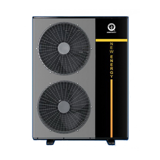
Page 4: Main Instruction Of Product
6. High efficiency heat exchanger, more evaporate paths, larger evaporate square, high coefficient、 wider fin space, better prevent from dust, stable ventilation, better prevent from frost; II. Main instruction of product 1.1 Main models and specification parameter of outdoor inverter series: Outdoor model BKDX30-95I/150/S BKDX50-200I/150/S Voltage(V/Hz/h) 220V/50Hz/1Ph 220V/50Hz/1Ph Refrigeration... - Page 5 Water drop 30 kPa 35 kPa heat exchanger Water pipe G1” inch G1” inch Rated flow rate 2.2 m3/h 3.5 m3/h Indoor unit Net size 500*240*600 mm 500*240*600 mm Indoor unit net weight 25Kg 26.5Kg With the outdoor unit BKDX30-95I/150/S(*1) BKDX50-200I/150/S(*1)
- Page 6 2.1Dimensions: 2.1.1 BKDX30-95I/150/S: 1041 2.1.2 BKDX50-200I/150/S: 1081 1023...
- Page 7 2.1.3 BKDX30-95I/150/Y1,BKDX50-200I/150/Y1: 1-G3/4" 2-G1" III. Installation (1).Installation location ◆ Provide sufficient space for installation and maintenance. ◆ Inlet and outlet accessibility, strong wind cannot reach ◆ Unit installed in ventilation place where can bear the weight of the unit, can mount the unit horizontally, also will not increase the mechanical noise and vibration.
- Page 8 (2).Installed in the following locations may cause the machine to malfunction. ◆ Places such as cutting oil and other mineral oils. ◆ Places with salted air near the sea. ◆ Places which contains gas such as sulfur, acidic or alkaline and other corrosive gases in the spa area.
- Page 9 (4).Selection circulation pipeline. Circulation pipeline of inverter heat pump can not be smaller than the inlet and outlet pipeline, circulation pipe should use the same diameter as inlet and outlet pipes. (5).Connection of pipeline Don't let the dust and other debris into piping system. ...
- Page 10 Notice: 1)Distribution piping pressure test should be a separate, do not with hot water units, tank pressure test together. 2)Working pressure of water system is 0.2-0.6Mpa. (6). Installation schematic diagram 1.1, BKDX50-200I/150/S 1.2, BKDX30-95I/150/S...
- Page 11 Notice:1)Water can be flow out from the drain pipe in the pressure relief device, and To keep drain open to atmosphere. 2)Pressure relief devices regularly running to remove calcium carbonate sediments and ensure device is not blocked. 3)when install check valve, filter and pressure relief devices, the valve arrow should have same direction as water flow.
- Page 12 Power supply wiring line (wire diameter selection) reference table: 1. Power wiring is control board’s wiring system to the diameter of the branch wiring devices reference value of each unit and circulating pump units. 2.Selection for the main Line is base on 1.25 times of the sum power of simultaneously operating device in the whole heating system 2.
-
Page 13: Trial Running
IV. Trial running 1.Trial running must after all the installation completed. 2.Please confirm the following matters before the trial operation, put “√”in the boxes after confirmation ▲ Unit is installed correctly ▲ Power supply meets unit’s rated power source need ▲... -
Page 14: V.operation Panel Instruction
V.Operation panel instruction 1. Indoor line control panel 2.Key Functions Notice : Wired control panel automatically locked without any key operation after 30S, the display showed the key lock , press button to lock or unlock. 1.1. ON / OFF button: Press to turn on / off the unit. - Page 15 then press " " key 3 seconds or press " " key to exit the refrigerant recovery modes, the icon does not display. 1.3. Clock setting button: 1.3.1 Setting the clock (hours: minutes) Press " " button, flashing signs, flashing minute display area, press again, hour flashing, press "UP", "DOWN"...
- Page 16 Always exit timer off time setting. 1.3.3 Cancel the timer After setting the timing, at unlocked state, press " " key to cancel the timer. 1.4. UP key: UP control key. 1.5. DOWN key: DOWN control key. 1.6. Set temperature adjustment When non-automatic mode, simply press enter to adjust the set temperature corresponding mode;...
- Page 17 d11. After throttling temperature Electronic expansion valve opening(displayed as the actual opening) 2.2 Timing function 2.2.1 Timing maximum range is 24 hours, a minimum resolution of 1min. 2.2.2 Regular boot function: When turned off, to set the timer on in automatic boot time, if already in the boot state, without treatment.
- Page 18 backlight turns off. 3.1.7 Display mode, the measured temperature : Depending on the operating mode corresponding to the display, in automatic mode, the temperature display to indicate the tank temperature, when the water temperature to the temperature, the display mode the measured temperature of the room.
- Page 19 Thermostat temperature difference 0℃~5℃ Electric heater starts time 1~120 minutes Electric heater starts ambient -20~20℃ temperature setting value Accumulated defrost time setting 1~120 minutes The heating mode enter into the 1~25℃ defrost ambient temperature Start defrost of the ambient 1~25℃ temperature and coil temperature difference -20~20℃...
- Page 20 reserve Antifreeze switch 0=Invalid 1=valid Model parameter selection 6. Unit fault code table Fault code Fault Name Outdoor unit current protection Flow switch protection EEPROM error indication (indoor board) / EEPROM error indication (operation panel) Return water temperature over high when heating or output water temperature over low when cooling DC link voltage is over high / low protection IPM failure...
- Page 21 7. Wiring diagram (1)BKDX50-200I/150/S-D (2)BKDX50-200I/150/YI-D...
- Page 22 (3)BKDX30-95I/150/S-D (4)BKDX30-95I/150/YI-D...
-
Page 23: Vi.maintenance & Repair
VI.Maintenance & Repair ● Maintenance: 1. The motor has been lubricate and sealed in advance before left the factory, therefore lubricate is not needed during maintenance. 2. Using a stiff nylon brush to clean the evaporator fins. Before scrub, clean it with vacuum cleaner. - Page 24 side. Use vacuum pump to vacuumize the system for more than 15 minutes. Then confirm if the vacuum gauge shows at -1.0×10⁵Pa(-76cmHg). b 、 After achieving the required vacuum effect, filling the refrigerant to the system with refrigerant bottle. On the nameplate and main technical parameters we have marked the suitable refrigerant.
- Page 25 PCB damaged Substitution method Replace PCB Transformer Measure with Replace transformer damaged multi-meter Operation panel Welding with soldering Check the circuitry lines not connected iron well operation panel Operation panel Substitution method Replace operation panel Machine does no display damaged not work PCB damaged Substitution method...
- Page 26 Measure with open circuit Replace the capacitor multi-meter Measure with short circuit Replace the capacitor multi-meter Motor winding open measure the Replace the motor circuit winding Motor winding short measure the measure the winding Motor damaged circuit winding Motor winding measure the measure the winding grounding...
-
Page 27: Accessories
Compressor oil Listen to the noisy fill refrigeration oil shortage, noisy, and test the excessive compressor Defrosting Short circuit Test the resistance Replace sensor temperature Open circuit Test the resistance Replace sensor sensor reinstall Resistance variation Test the resistance Replace sensor after broken Defrosting temperature sensor loose Check the sensor...
Need help?
Do you have a question about the BKDX30-95I/150/S and is the answer not in the manual?
Questions and answers