Advertisement
Advertisement
Table of Contents

Subscribe to Our Youtube Channel
Summary of Contents for NEW ENERGY NE-B245/100E
- Page 1 DC INVERTER HEAT PUMP Installation And Operation Instruction...
-
Page 2: Table Of Contents
CONTENT I. Prologue................3 II. Parameters................4 1. Parameters..............4 2. Appearance..............4 3. Attention................ 4 III. Main introduction of product......... 5 IV. Installation................ 5 1. Installation..............6 2. Piping diagram.............8 3. Circuit connection............8 V. Trial operation..............12 VI. Control system instruction.......... 13 1. - Page 3 Please read this manual carefully before using our products. And please install and operate the machine in accordance with this manual, otherwise, we will not responsible for any loss. ◆This heat pump water heater must be installed by the professional technical personnel. ◆Please install the machine and connect the water pipe in accordance with this manual strictly.
-
Page 4: Prologue
I. Prologue Thanks for using air source heat pump water heater! Please read this manual carefully before installation and operation. There are information for installation, operation, maintenance, commissioning. High design and production standard make sure air source heat pump water heater running safely and ... -
Page 5: Parameters
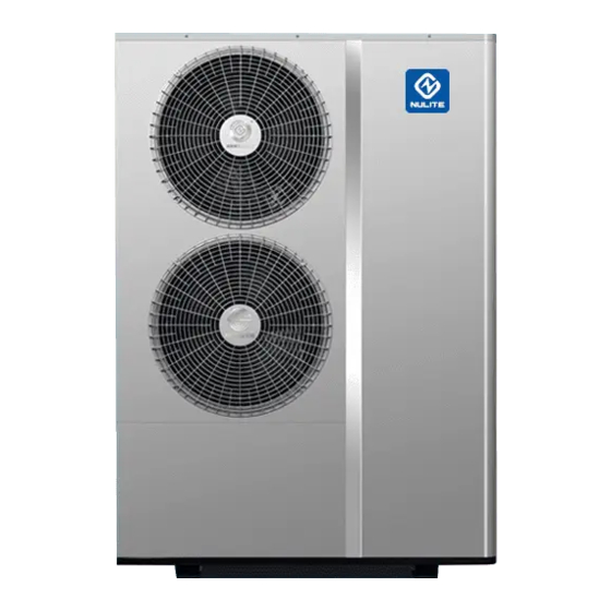
II. Parameters 1. Parameters Model Size (length*width*height)mm N.W. / G.W.(kg) Power source NE-B245/100E 900×350×1250 75/80 220V~50Hz/60Hz NE-B345/100E 965×354×1346 110/115 220V~50Hz/60Hz 2. Appearance 3. Attention 3.1 Please read the manual carefully before installation and using. It included all information related to correct installation, debugging, operation, and maintenance. -
Page 6: Main Introduction Of Product
III. Main introduction of product 1. Detail parameters Item DC Inverter instant heating heat pump Model NE-B245/100E NE-B345/100E Level of security IPX4 Electric shock protection grade Ⅰ Rated power 220V~50Hz/60Hz Rated output water volume 245L/h 345L/h Tank volume Rated heating capacity... -
Page 7: Installation
1. Installation 1.1 installation position The place should have enough space for installation & maintenance. None block to the air inlet and outlet and none strong wind or hurricane could reach. The place should well-ventilate, solid, there should be no extra running noise or vibration noise after loading the unit. - Page 8 1) Safety relief valve should install on the inlet of the water tank. 2) The drain pipe of safety relief valve should keep open with atmosphere. 3) Safety relief valve should work regularly, so as to get rid of the calcium carbonate and to approval the device hasn’t block.
-
Page 9: Piping Diagram
2. Piping diagram 3. Circuit connection 3.1 Attention Before installation, please confirm whether your local voltage is match with the voltage showed on the machine’s nameplate and whether the carrying capacity of the power supply, wires and sockets are suitable for this machine’s input power. - Page 10 The minimum conductor cross-section Rated current/A cross-section/mm ≤0.2 tinsel cordª 0.5ª >0.2&≤3 0.75 >3&≤6 1.0(0.75) >6&≤10 1.5(1.0) >10&≤16 >16&≤25 >25&≤32 >32&≤40 >40&≤63 A. The length of the wire and the wire protective sleeve is less than 2m that can use this type of wire. B.
- Page 11 3.2 Electric wiring diagram 3.2.1 NE-B245/100E Orange Orange Black Black White White HEATB HEATC FANLFANH Yellow/Green White Yellow/ Green Wire controller FU1 T20AH 250V Black Black White EEV1 compressor power input (220VAC/50-60Hz) 110070147...
- Page 12 3.2.2 NE-B345/100E Inductor OUT7 OUT6 OUT3 OUT2 OUT1 Yellow/Green COM1 AC_N COM2 T30AH250V TS3 TS4 AC_L TH1 TH2 TH3TH4TH5 TH6 JTAG Black W hite Yellow/Green W ired controller Electronic expansion valve Power input ( 220V/1PH/50Hz/60Hz)
-
Page 13: Trial Operation
V. Trial operation Check before operating A. Trial running must after all the installation is completed. B. Please confirm the following matters before the trial operation, put “√”in the boxes after confirmation: ● Unit is installed correctly ● Power supply meets unit’s rated need ●... -
Page 14: Control System Instruction
VI. Control system instruction 1. Operation illustration 1.1 displays... - Page 15 1.2 wired controller display declaration 1.2.1 Temperature display area display system cock,timing ,running parameters, common parameters, alarm code related datas.Left side temperature display area display actual detect tank temperature ,setting temperature ,parameter number etc.right side temperature display area display setting temperature ,parameters values etc.
- Page 16 1.3.6.1 Enter setting ;first pressing “ ” then press “ ” for 3 secs,the temperature display area display “00” and blinking display ,input the password (default password “Fb”),then press “ ”or “ ”to add or subtract ,press “ ”or “ ”...
- Page 17 hour position blinking display , press “ ”or “ ”to modify hour value ,press “ ” to confirm and “1 ”、 “OFF ”symbols blinking display .the minute position blinking display ,press “ ”or “ ”to modify minute value ,then press “ ”...
-
Page 18: Maintenance
VII. Maintenance 1.Maintenance protection 1.1 Using a stiff nylon brush to clean the evaporator wings. Before scrub, clean it with vacuum cleaner. If there is compressed air, you can use high pressure air to clean the condenser or evaporator. 1.2 Periodic inspecting if the air inlet or outlet is stopped up. 1.3 Pay close attention to the outlet, inlet/ suction pressure of the system. - Page 19 Compressor(input) Excessive current Return gas sensor fault fault Reserved Exhaust gas temp.overhigh protection LP switch abnormal failure Winter antifreeze protection HP switch abnormal failure A70-A93 IPM module protection Reserved 2.2 solutions phenomenon reason check clear The machine does 1: Operation panel line 1: Check the line;...
- Page 20 compressor lower than the water 3: Alternative Method; 3: Change electronic control terminals without temperature; 4: Alternative Method; board is broken; power (electric 3:The electronic control 5: Measuring line voltage 4: Change transformers; control panels no board is broken; 5: Wait to restore power voltage output) 4: Transformer is broken;...


Need help?
Do you have a question about the NE-B245/100E and is the answer not in the manual?
Questions and answers