Table of Contents
Advertisement
Quick Links
Advertisement
Table of Contents

Related Manuals for Norsat WAYFARER KU-BAND WFA120KU-EU


Summary of Contents for Norsat WAYFARER KU-BAND WFA120KU-EU
- Page 1 USER MANUAL WAYFARER 1.2M KU-BAND AUTO-ACQUIRE FLY-AWAY ANTENNA...
-
Page 3: Table Of Contents
TABLE OF CONTENTS Copyright Notice ............................4 Revision History............................5 Cautions ..............................5 Acronyms..............................5 List of Contents............................6 Case 1 ..............................6 Case 2 ..............................7 1. Overview............................... 8 1.1 Manual Contents ..........................8 2. System Overview..........................8 2.1 System Block Diagram ........................8 3. -
Page 4: Copyright Notice
Copyright © 2019. Norsat International Inc. All rights reserved. All materials contained in this user guide are the property of Norsat International Inc. except as noted here below: All materials in this user guide are protected by United States and international copyright laws. The compilation of all content in this user guide is the exclusive property of Norsat. -
Page 5: Revision History
Antenna Gain Control for DVB signal strength bAGC Antenna Gain Control for beacon signal strength M&C Monitor and Control Interfacility Link Orthomode Transducer Low-noise Block Downconverter Block Upconverter Local Oscillator Counter clockwise Clockwise DOC-000848 Rev A 10/2019 © 2020 Norsat International Incorporated (“Norsat”) All Rights Reserved... -
Page 6: List Of Contents
Sensor cable for compass Firmware upgrade cable RS232 (DB9) cable for ACU firmware upgrade Case 1 Pedestal Assembly with BUC and Remote Cable Modem Cable Leg Assembly Antenna Power Supply Footpad x3 Sensor Cable DOC-000848 Rev A 10/2019 © 2020 Norsat International Incorporated (“Norsat”) All Rights Reserved... -
Page 7: Case 2
Case 2 Feed Horn Petals (5 to 8) Firmware upgrade cable IFL cable (optional) Petals (1 to 4) BUC Power Supply (optional) DOC-000848 Rev A 10/2019 © 2020 Norsat International Incorporated (“Norsat”) All Rights Reserved... -
Page 8: Overview
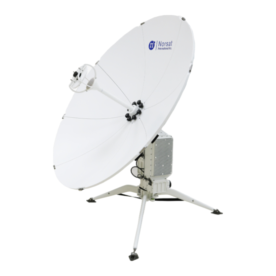
1. Overview The Norsat WAYFARER is an industrial strength transportable satellite communication system built strong for the most demanding users working with the most challenging applications and environments. The WAYFARER is fully automated, integrated, and versatile enough for deployment virtually anywhere, including mobile field offices, field vehicles, or directly on the ground. A complete satellite solution, the WAYFARER includes everything to meet your communication needs. -
Page 9: Hardware
Case 1 (Pedestal, Tripod) 846mm x 620mm x 490mm 34 Kg Case 2 (Feed, Petal) 846mm x 620mm x 490mm 27Kg + accessories (up to 10 Kg) DOC-000848 Rev A 10/2019 © 2020 Norsat International Incorporated (“Norsat”) All Rights Reserved... - Page 10 Fiberboard Case 848.82 1242 Side view of antenna after assembly when stowed (in: mm) 1200 DOC-000848 Rev A 10/2019 © 2020 Norsat International Incorporated (“Norsat”) All Rights Reserved...
-
Page 11: Electrical
BUC up to 8W can be powered by 24V DC from modem through IFL cable 20W and 40W ATOM BUC requires 48V DC input from at least 300W power supply DOC-000848 Rev A 10/2019 © 2020 Norsat International Incorporated (“Norsat”) All Rights Reserved... -
Page 12: Power Supply
Power switch for antenna Rx signal output from LNB Tx signal input for BUC DC IN 24V DC power input, to be connected to supplied AC power adapter DOC-000848 Rev A 10/2019 © 2020 Norsat International Incorporated (“Norsat”) All Rights Reserved... -
Page 13: Introduction To System Components
ACU. The heading information is updated upon system reset. 4.3.5 Modem Port The modem port is designed to be integrated with iDirect Modems. The ACU outputs the GPS signal DOC-000848 Rev A 10/2019 © 2020 Norsat International Incorporated (“Norsat”) All Rights Reserved... -
Page 14: Adjustment Knobs
Push button on quick Ensure the spring pin Take footpads from Insert leg joint into release pin to insert from goes through mounting Case 1 footpad from top side hole DOC-000848 Rev A 10/2019 © 2020 Norsat International Incorporated (“Norsat”) All Rights Reserved... - Page 15 At this stage, your assembled terminal should look like what is displayed in Figure A: Feed Cover Feed Collar Locating Pin Slot Figure A DOC-000848 Rev A 10/2019 © 2020 Norsat International Incorporated (“Norsat”) All Rights Reserved...
- Page 16 The latch will be facing connected to each other. the ground. Your assembled WAYFARER is now ready for cable connection and should appear as seen below: Latch DOC-000848 Rev A 10/2019 © 2020 Norsat International Incorporated (“Norsat”) All Rights Reserved...
-
Page 17: Cable Connection
Modem Console port Modem cable Remote Control REMOTE Controller Laptop Remote cable Connect power supply to AC power source with 100-240VAC. Connection Diagram OpenAMIP Modem: Connection Diagram Non-OpenAMIP Modem: DOC-000848 Rev A 10/2019 © 2020 Norsat International Incorporated (“Norsat”) All Rights Reserved... -
Page 18: Auto-Acquire Through Linkcontrol (Non-Openamip)
- If signal level reading is below the threshold during pointing, the user may lower the signal level threshold or raise the magnification to avoid failure in pointing. Once Pointing is completed, system status will show as Auto-Acquire completed. Note: The BUC requires a 10 MHz reference in order to transmit. DOC-000848 Rev A 10/2019 © 2020 Norsat International Incorporated (“Norsat”) All Rights Reserved... -
Page 19: Auto-Acquire Through Linkcontrol (Openamip)
Select Abort to prevent the auto- acquire from initiating and to place the Antenna in User Controlled Mode (Refer to Auto-Acquisition (Non-OpenAMIP) for more details) DOC-000848 Rev A 10/2019 © 2020 Norsat International Incorporated (“Norsat”) All Rights Reserved... - Page 20 - If signal level reading is below the threshold during pointing, the user may lower the signal level threshold or raise the magnification to avoid failure in pointing. If desired, navigate to the Modem page to get information on the current modem parameters DOC-000848 Rev A 10/2019 © 2020 Norsat International Incorporated (“Norsat”) All Rights Reserved...
-
Page 21: Software
Click “Change adapter settings Right click the Ethernet adapter and click “Properties” Select “Internet Protocol Version 4 From there, the Ethernet Adapter’s (TCP/IPv4) and click “Properties” properties can be configured as needed DOC-000848 Rev A 10/2019 © 2020 Norsat International Incorporated (“Norsat”) All Rights Reserved... - Page 22 Note: If using two ethernet adapters, instead add the two IP addresses to the different ethernet adapters. 6.1.2 Device Configuration WARNING: Incorrectly specifying a device’s communication settings can lead to LinkControl not being able to work properly. 6.1.2.1 Basic Device Configuration Launch the Device Manager by going Administration → Device Manager DOC-000848 Rev A 10/2019 © 2020 Norsat International Incorporated (“Norsat”) All Rights Reserved...
- Page 23 Afterwards, press the “Refresh” button to update the selection options. 6.1.2.2 Advanced Device Configuration 6.1.2.2.1 Going to “Advanced View” WARNING: Using controls displayed in “Advanced View” can result in LinkProfiles becoming invalid, hardware malfunctioning and configuration information getting permanently lost. Proceed with caution. Launch the Device Manager by going Administration → Device Manager DOC-000848 Rev A 10/2019 © 2020 Norsat International Incorporated (“Norsat”) All Rights Reserved...
- Page 24 Device Manager 6.1.2.2.3 Editing an Existing Device WARNING: Incorrectly editing an existing device can result in LinkProfiles becoming invalid, hardware malfunctioning and configuration information getting permanently lost. Proceed with caution. Select the device that you wish to edit in the Device Manager and press “Edit Device” DOC-000848 Rev A 10/2019 © 2020 Norsat International Incorporated (“Norsat”) All Rights Reserved...
- Page 25 Select the device that you wish to remove in the Device Manager and press “Remove Device” When prompted for confirmation, select “Yes” if you’d like to proceed. DOC-000848 Rev A 10/2019 © 2020 Norsat International Incorporated (“Norsat”) All Rights Reserved...
-
Page 26: Satellite Almanac
6. Add any new known beacons and carriers on the satellite using the Satellite Almanac interface and clicking on the Add Carrier button to the right of the List of Satellite Carriers. DOC-000848 Rev A 10/2019 © 2020 Norsat International Incorporated (“Norsat”) All Rights Reserved... - Page 27 3. LinkControl stores these satellites so be aware that secure satellites can be retrieved 4. DVB carriers and beacons may be changed, so update your almanac regularly DOC-000848 Rev A 10/2019 © 2020 Norsat International Incorporated (“Norsat”) All Rights Reserved...
-
Page 28: Linkprofiles
Change the LinkProfile name. o Make any other desired changes to the LinkProfile. o Click on the Save As A New LinkProfile button to save the new LinkProfile. To create or edit a LinkProfile: 1. Click the LinkProfiles navigation button on the left side of the screen to bring up the LinkProfile Settings Screen. • To create a new LinkProfile, click on the Add New LinkProfile button. • To edit an existing LinkProfile, ensure that the LinkProfile has been selected in the LinkProfile List and then click on the Edit LinkProfile button. DOC-000848 Rev A 10/2019 © 2020 Norsat International Incorporated (“Norsat”) All Rights Reserved... - Page 29 If using an OpenAMIP modem, skip ahead to Step 12 From the “Select Satellite and Carrier” form, choose a target satellite and optionally, a target carrier and press “Update” when done. DOC-000848 Rev A 10/2019 © 2020 Norsat International Incorporated (“Norsat”) All Rights Reserved...
-
Page 30: Status Monitoring
The alarm entries at the bottom of the main user interface will keep you updated of major system occurrences and a troubleshooter is provided to assist with resolving any issues. DOC-000848 Rev A 10/2019 © 2020 Norsat International Incorporated (“Norsat”) All Rights Reserved... - Page 31 To view detailed system status, click on the Status navigation button. The Status Screen displays information on the polarization, elevation and azimuth angles, limit switch status, GPS reading and compass readings. DOC-000848 Rev A 10/2019 © 2020 Norsat International Incorporated (“Norsat”) All Rights Reserved...
-
Page 32: Openamip Vs Non-Openamip Mode
Note: Auto-Acquisition to last satellite can be initiated with holding the One Button on the ACU and release it after hearing 2 beeps. Note: LinkControl compensates for uneven terrain up to 15 degrees, but the more level the system is the faster your acquisition. DOC-000848 Rev A 10/2019 © 2020 Norsat International Incorporated (“Norsat”) All Rights Reserved... -
Page 33: Auto-Acquisition (Openamip)
Stopping, resetting or stowing the antenna can all cause LinkControl to switch out of OpenAMIP mode The OpenAMIP Modem page can be used to change back to OpenAMIP Mode (or be used to see additional modem specific information) DOC-000848 Rev A 10/2019 © 2020 Norsat International Incorporated (“Norsat”) All Rights Reserved... - Page 34 - If the signal level reading remains 0 during pointing, it’s possible that the auto-acquire process is using an inactive beacon or carrier. Once the auto-acquire fails, LinkControl will automatically try another auto-acquire using a different beacon or carrier on the same satellite. DOC-000848 Rev A 10/2019 © 2020 Norsat International Incorporated (“Norsat”) All Rights Reserved...
-
Page 35: Motor Control
Click on the Alignment navigation button to bring up the movement control page. Go To Target Angle buttons can be used to initiate movement to the desired orientation. DOC-000848 Rev A 10/2019 © 2020 Norsat International Incorporated (“Norsat”) All Rights Reserved... - Page 36 Note: In any instance of motor failure, the user may manually adjust the Az/El angles by rotating the knobs on the pedestal and adjust the polarization by rotating the rotary joint near OMT directly. DOC-000848 Rev A 10/2019 © 2020 Norsat International Incorporated (“Norsat”) All Rights Reserved...
-
Page 37: System Troubleshooting
Invalid Command Syntax The client is sending commands with invalid syntax to the server Please contact the terminal manufacturer if this issue persists after power cycling the terminal DOC-000848 Rev A 10/2019 © 2020 Norsat International Incorporated (“Norsat”) All Rights Reserved... - Page 38 Check the cable connections inside the ACU for the Beacon receiver Connected Once the issue has been fixed, the system must be power cycled to clear the alarm Please contact the terminal manufacturer if this issue persists after power cycling the terminal DOC-000848 Rev A 10/2019 © 2020 Norsat International Incorporated (“Norsat”) All Rights Reserved...
-
Page 39: System Maintenance
Connect the antenna to power. While pressing ‘One Button’, press ‘On/Off’ button to turn on system. Do not release ‘One Button’ until system beeps twice. The system is now reset to factory settings. All limit switch information and encoder calibration information will be restored. DOC-000848 Rev A 10/2019 © 2020 Norsat International Incorporated (“Norsat”) All Rights Reserved... -
Page 40: Technical Specifications
DC24 10A, AC110-230V 50/60Hz 5A (optional) Work wind load Can work under 10m/s (with ballast weight), and no damage under 17m/s. Temperature -40˚C to +60˚C Protection grade IP65 Humidity 0-95% DOC-000848 Rev A 10/2019 © 2020 Norsat International Incorporated (“Norsat”) All Rights Reserved... -
Page 41: Appendix A - Magnetic Declination Map
Appendix A - Magnetic declination Map US/UK World Magnetic Model - Epoch 2015.0 Main Field Declination. (2014, December). Retrieved from http://ngdc.noaa.gov/geomag/WMM DOC-000848 Rev A 10/2019 © 2020 Norsat International Incorporated (“Norsat”) All Rights Reserved... -
Page 42: Appendix B - Default Antenna Settings
Motor Speed 6.00 How quickly the motor moves, in degrees per second Coarse Nudge Offset 5.00 How far the motor moves when performing a coarse nudge DOC-000848 Rev A 10/2019 © 2020 Norsat International Incorporated (“Norsat”) All Rights Reserved... - Page 43 Offset added to the Compass’s pitch Roll Compensation 0.00 Offset added to the Compass’s roll Transmit Enabled By Antenna Whether or not transmit is enabled by the antenna when in OpenAMIP mode DOC-000848 Rev A 10/2019 © 2020 Norsat International Incorporated (“Norsat”) All Rights Reserved...
- Page 44 Wind load - Operational Wind load - Survival 61 km/h 65 km/h 100 km/h Temperature -40˚C to +60˚C -40˚C to +60˚C -40˚C to +60˚C Humidity 0-95% (20˚) 0-95% (20˚) 0-95% Water Ingress IP 65 IP 65 IP 65 DOC-000848 Rev A 10/2019 © 2020 Norsat International Incorporated (“Norsat”) All Rights Reserved...
- Page 45 80 km/h 65 km/h 90 km/h 90 km/h 201 km/h -40˚C to +60˚C -40˚C to +55˚C -40˚C to +55˚C -40˚C to +60˚C 0-100% with Conden- 0-95% (20˚) 0-95% 5-95% sation IP 65 IP 65 IP 65 Specifications are subject to change without notice DOC-000848 Rev A 10/2019 © 2020 Norsat International Incorporated (“Norsat”) All Rights Reserved...
- Page 46 ABOUT NORSAT Norsat International Inc., founded in 1977, is a leading provider of innovative communication solutions that enable the transmission of data, audio and video for remote and challenging applications. Norsat’s products and services include customizable satellite components, portable satellite...