Table of Contents
Advertisement
Quick Links
Advertisement
Table of Contents
Troubleshooting

Related Manuals for Norsat GLOBE TREKKER


Summary of Contents for Norsat GLOBE TREKKER
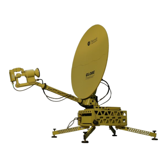
- Page 1 USER MANUAL GLOBE TREKKER ASSEMBLY MANUAL...
- Page 2 Norsat does not assume any liability arising out of the application or use of any product or circuit described herein. Norsat does not convey any license under its patent rights or the rights of others.
-
Page 3: Table Of Contents
Software Troubleshooter ..............30 Hardware Issues ..................31 X-Band Feed Polarization ................... 35 Changing the Feed Polarization ..............35 Manual Acquisition..................... 37 5.1 Operating the GLOBETrekker™ without Motors ..........37 © Norsat International Inc. (“Norsat”) All Rights Reserved 2021-03-22 037685 Rev B... - Page 4 Table 1: Sample Clearance Distance Calculations ............8 Table 2: Minimum Ballast Required per Leg ..............9 Table 3: Status Indicators ....................30 Table 4: Troubleshooting ....................31 © Norsat International Inc. (“Norsat”) All Rights Reserved 2021-03-22 037685 Rev B...
- Page 5 3. Never place any part of your body in line with the direction of the antenna transmission path. 4. Locate the terminal as far as possible from ungrounded metal. © Norsat International Inc. (“Norsat”) All Rights Reserved 2021-03-22 037685 Rev B...
- Page 6 Use of non-approved accessories or devices may lead to a degradation in performance, damage to equipment, or potential hazards Servicing the Equipment Do not service the equipment alone unless another person is present to administer first-aid © Norsat International Inc. (“Norsat”) All Rights Reserved 2021-03-22 037685 Rev B...
- Page 7 Preface Purpose and Scope of the User Guide The user guide explains the system specifics of the Norsat GLOBETrekker™ satellite terminal. This user guide is specifically written for the 1.0m GLOBETrekker™ Audience The guide will be of interest to the following personnel: •...
-
Page 8: Positioning The System
2. Ensure that there is a clear view of the sky towards the equator and target satellite a. You can use a product like Norsat’s Satellite Finder to assist in checking for view angles. 3. Ensure that you have access to sufficient power 4. -
Page 9: High Wind Set-Up
1.2m Ballast (kg) * * Note: the specified ballasts are assumed to be applied directly on top of the footpad. If the ballast is applied further up the leg then the mass must be increased. Contact Norsat for details. 2. Assembling the System This chapter details the steps necessary to assemble a GLOBETrekker ™... -
Page 10: Figure 2: Backside Of The Baseband Unit
Hook the legs into the slots of the brackets. Ensure the locating pins on the brackets are aligned with the slots in the legs. Assemble so that the legs are flat on the bracket. Secure the legs using thumbscrews. © Norsat International Inc. (“Norsat”) All Rights Reserved 2021-03-22 037685 Rev B... -
Page 11: Figure 3: Supporting Legs And The Bracket
Example: If your position is north of the equator, place the unit with the front facing the South. Level the BBU using the threaded feet on the quad pod legs. The spirit level in the top of the unit will assist in the leveling process. © Norsat International Inc. (“Norsat”) All Rights Reserved 2021-03-22 037685 Rev B... -
Page 12: Assembling The Main Antenna Unit
Ensure that you do not mix components from the provided kits. Remove the appropriate backplate from the components case you are installing and remove Elevation Lock Pin (if installed). © Norsat International Inc. (“Norsat”) All Rights Reserved 2021-03-22 037685 Rev B... -
Page 13: Figure 6: Rf Backplate And Elevation Lock Pin
Figure 6: RF Backplate and Elevation Lock Pin Fold the backplate support arms to bring the RF backplate to the standing position. Figure 7: Fold the Supporting Arms of the RF Backplate © Norsat International Inc. (“Norsat”) All Rights Reserved 2021-03-22 037685 Rev B... -
Page 14: Figure 8: Install The Backplate Onto The Baseband
Important: Do not rest the RF backplate on the Baseband cables; ensure that the cables rest fully behind the backplate. Secure the backplate using the elevation lock pins. © Norsat International Inc. (“Norsat”) All Rights Reserved 2021-03-22 037685 Rev B... -
Page 15: Assembling The Elevation Motor
Note the orientation: • For DC Motor, the motor sits to the outside of the structure. • For Stepper Motor, the cable sits to the outside of the structure. © Norsat International Inc. (“Norsat”) All Rights Reserved 2021-03-22 037685 Rev B... -
Page 16: Assembling The Antenna Reflector
The assembly order of the petals may vary slightly depending on the type of reflector supplied with the system. Refer to the photos below for a summary of the assembly order: © Norsat International Inc. (“Norsat”) All Rights Reserved 2021-03-22 037685 Rev B... -
Page 17: Figure 10: Assembly Steps Of The Antenna Reflector
Remove Segment 1 from the reflector petal bag and rest it on the RF backplate. Figure 11: Install Segment 1 Reflector Petal on the Backplate Attach the Petal to the RF backplate using the thumbscrews. Loosely attach all four screws before tightening. © Norsat International Inc. (“Norsat”) All Rights Reserved 2021-03-22 037685 Rev B... -
Page 18: Figure 12: Secure Segment 1 Reflector Petal Using The Thumbscrews
Figure 12: Secure Segment 1 Reflector Petal Using the Thumbscrews Attach Segment 2 to the bottom left of the main antenna unit. Figure 13: Install Segment 2 Reflector Petal © Norsat International Inc. (“Norsat”) All Rights Reserved 2021-03-22 037685 Rev B... -
Page 19: Figure 14: Install Segment 3 Reflector Petal
Attach Segment 3 to the bottom right of the central antenna unit. Figure 14: Install Segment 3 Reflector Petal © Norsat International Inc. (“Norsat”) All Rights Reserved 2021-03-22 037685 Rev B... -
Page 20: Figure 15: Assemble Segment 4,5, And 6 Reflector Petals Together
Attach Segments 4,5 and 6 together on their own (do not attach to segments 1, 2, or 3 at this time) Figure 15: Assemble Segment 4,5, and 6 Reflector Petals together © Norsat International Inc. (“Norsat”) All Rights Reserved 2021-03-22 037685 Rev B... -
Page 21: Figure 16: Install The Two Halves Reflector Together
Attach the two halves together. Figure 16: Install the Two Halves Reflector Together © Norsat International Inc. (“Norsat”) All Rights Reserved 2021-03-22 037685 Rev B... -
Page 22: Assembling Boom Arm And Feed
Loop the cable over the boom arm once to prevent the cable from snagging or dragging. Note: Leave enough slack in the LNB cable to allow the LNB to rotate freely. © Norsat International Inc. (“Norsat”) All Rights Reserved 2021-03-22 037685 Rev B... - Page 23 Loop the cable over the boom arm once to prevent the cable from snagging or dragging. Coil and secure the excess cables on the Azimuth plate using the Velcro strap. © Norsat International Inc. (“Norsat”) All Rights Reserved 2021-03-22 037685 Rev B...
-
Page 24: Connecting Main Antenna Cables
Connect the M&C and DC Input connector(s) to the BUC/SSPA Connect the Red TX cable to the N- Connector at the top of the BUC/SSPA © Norsat International Inc. (“Norsat”) All Rights Reserved 2021-03-22 037685 Rev B... -
Page 25: Assembling The Struts (Optional)
Figure 18: Install the Structs 2.9 Connecting Peripherals to your System 2.9.1 Daylight Readable Touch Screen Display Connect the Daylight readable touch screen display to the monitor port of the [Subject] Base. © Norsat International Inc. (“Norsat”) All Rights Reserved 2021-03-22 037685 Rev B... -
Page 26: External Modems
Figure 19: Connect LCD Touchscreen to Baseband 2.9.2 External Modems Norsat VSAT systems work with L-Band frequency RF components. When deploying a modem or video encoder with a [Subject] ensure that it operates in this frequency band. External Modems should be set up according to the manufacturer’s instructions. -
Page 27: Figure 21: Tx And Rx Port On The External Modem
Warning: The [Subject] cannot operate with both coaxial and fiber optic at the same time. Doing so may cause damage to the internal components. Note: If your system has an internal modem, ensure that it has been disabled using your LinkControl software. © Norsat International Inc. (“Norsat”) All Rights Reserved 2021-03-22 037685 Rev B... -
Page 28: Powering On The System
To view the system status select the “Status” icon from the left-hand toolset. Major system component health will be presented in real time. Some components have a simple alarm icon with a detail button to retrieve extra information. © Norsat International Inc. (“Norsat”) All Rights Reserved 2021-03-22 037685 Rev B... -
Page 29: Figure 24: System Status
Figure 24: System Status © Norsat International Inc. (“Norsat”) All Rights Reserved 2021-03-22 037685 Rev B... -
Page 30: Software Troubleshooter
A pop-up window will give the user a list of actions that should be attempted to resolve the issue © Norsat International Inc. (“Norsat”) All Rights Reserved 2021-03-22 037685 Rev B... -
Page 31: Hardware Issues
Allow the internal fans and heaters to run for a while, to improve internal environmental condition. © Norsat International Inc. (“Norsat”) All Rights Reserved 2021-03-22 037685 Rev B... - Page 32 Confirm the GPS is connected “Timed Out. Could Not Read (on the azimuth plate). GPS” message. GPS signal interference. Make sure you are in clear sky, not next to a wall. © Norsat International Inc. (“Norsat”) All Rights Reserved 2021-03-22 037685 Rev B...
- Page 33 (Either antenna is cable is plugged in, then power obstructed or elevation cycle the system. move command was sent while cable was unplugged) © Norsat International Inc. (“Norsat”) All Rights Reserved 2021-03-22 037685 Rev B...
- Page 34 10MHz reference line. and restart the Baseband. remains at start up power. - Alternately go to Tools- >Administration->System Panel and use the Environmental Control to power cycle the modem itself. © Norsat International Inc. (“Norsat”) All Rights Reserved 2021-03-22 037685 Rev B...
-
Page 35: X-Band Feed Polarization
To change the Feed to LEFT-HAND TRANSMIT, remove the 6x socket-cap screws (#8) from the Polarizer using the 9/64” ball-end hex driver provided with the system. 6 socket-cap screws to remove. Figure 26: Location of the 6 socket-cap screws to remove. © Norsat International Inc. (“Norsat”) All Rights Reserved 2021-03-22 037685 Rev B... -
Page 36: Figure 27: Apply A New Line Of Silver Grease
“LHCP” label facing up, indicating LHCP Figure 28: X-Band Feed Left-Hand Transmit Re-assemble the Polarizer to the Waveguide using the dowel pins for alignment. Install and tighten all 6 socket-head cap screws. © Norsat International Inc. (“Norsat”) All Rights Reserved 2021-03-22 037685 Rev B... -
Page 37: Manual Acquisition
3. For Ku-band systems, rotate the feed to adjust the polarization setting until the value matches the Transmit Polarization value shown in LinkControl. Figure 30: Rotate the Feed to Adjust the Polarization © Norsat International Inc. (“Norsat”) All Rights Reserved 2021-03-22 037685 Rev B... -
Page 38: Figure 31: Adjust The Elevation Manually
Tip: Depending on the azimuth value that is required, you may find it easier to lift the system and turn it so that it is within range of the required azimuth, and then fine tune the setting using the hand wheel. © Norsat International Inc. (“Norsat”) All Rights Reserved 2021-03-22 037685 Rev B... - Page 39 Fortune 1000 companies. 110 – 4020 Viking Way | Richmond | British Columbia | Canada V6V 2L4 | support@norsat.com www.norsat.com © Norsat International Inc. (“Norsat”) All Rights Reserved 2021-03-22 037685 Rev B...