Table of Contents
Advertisement
Quick Links
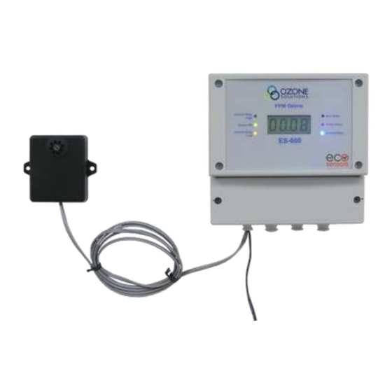
The ES-600 is an industrial grade ozone controller and monitor. The ES-600 design is optimized
for accuracy and ease of installation, setup and operation.
•
Front panel digital LCD displays ozone level.
•
Rugged, splash resistant NEMA 4X enclosure for
industrial environments.
•
Easily
accessible
controls allow the unit to be setup after it is
mounted.
•
LED indicators display when ozone exceeds the
0.1 ppm OSHA limit and a variety of other
important ozone control parameters.
•
Set points for ozone generator control relays are
digitally controlled with numeric set points. This
makes precise ozone control easy to set up, even
when ozone is not present.
•
Ozone generator failure mode detection warns when the connected ozone generator is not
maintaining the desired ozone set points. This option can be disabled.
•
"Monitor Mode" can be enabled on the ES-600 panel. This mode disables the ozone generator
controller and generator failure mode status indicators while maintaining ozone measurement
and limit warning indicators.
•
Analog outputs (4-20 mA and 0-2 VDC) are compatible with PLCs and other process
controllers.
•
Digital serial output (RS-232) allows for convenient connection to a computer. Data output:
ozone (ppb), temperature (°C), and relative humidity (%).
Ozone Solutions
sales@ozonesolutions.com
(888) 892‐0303
OZONE SWITCH
Model ES-600
ES-600 Features
connection
terminals
Ozone Controller, Model ES-600
and
User Manual, Rev. 1.0
1
Advertisement
Table of Contents

Summary of Contents for Ozone Solutions ES-600
- Page 1 OZONE SWITCH Model ES-600 ES-600 Features The ES-600 is an industrial grade ozone controller and monitor. The ES-600 design is optimized for accuracy and ease of installation, setup and operation. • Front panel digital LCD displays ozone level. • Rugged, splash resistant NEMA 4X enclosure for industrial environments.
- Page 2 TB4 will never run. Remove the jumper or replace it with a switch to disable the ozone generator when performing maintenance. Also remove the jumper to operate the ES-600 in “Monitor Mode”. In this state, when the , just jumper is removed, the Generator Control relay (TB4) will be disabled, as well as the “Generator Control”...
- Page 3 Initial Operation & Warm-Up All standard connections between the ES-600 and the SM-module are made at the factory. Once power is connected to the ES-600 using one of the methods described above, the green power/data LED will illuminate and then blink at a 1-second interval as data is received from the SM- module.
- Page 4 Data Connection Data from the ES-600 and connected SM-module can be received by a computer via RS-232 Serial Communication Parameters serial cable. Basic communication parameters are listed in the table to the right. For more details please consult RS-232 Communication...
- Page 5 If a defect develops during the warranty period, Ozone Solutions, in its sole discretion, will repair the instrument or replace it with a new or reconditioned model of equivalent quality.
- Page 6 Appendix A SM-Module Wiring Illustration #1 (Typical) ES-600 Wiring Compartment Panel Use either Power In 3-Wire Cable Power Out GND 12-24 VDC Data In GND 5VDC User Replaceable Sensor Connects Here WARNING: Never connect ES- 600 TB9: +12-24 V to SM-module TB1.
- Page 7 ES-600 Wiring Options Illustration Analog Outputs to Process Controller 4-20 mA Out Serial RS-232 0-2 VDC Out ES-600 Wiring Compartment Panel Use either N/O COM N/C Generator Control Relay Refer to SM-Module Wiring Illustrations N/O COM N/C TB7 Options: Alarm Relay: No Connection Monitor Mode Above 0.1 ppm OSHA Safety Limit...
Need help?
Do you have a question about the ES-600 and is the answer not in the manual?
Questions and answers