
Related Manuals for Clemco HOLLO-BLAST

Summary of Contents for Clemco HOLLO-BLAST
- Page 1 Owner´s manual HOLLO-BLAST INTERNAL-PIPE BLAST TOOL Clemco +49 (0) 8062 – 90080 International GmbH Carl-Zeiss-Straße 21 Tel.: 83052 Bruckmühl Mail: info@clemco.de Germany Web: www.clemco-international.com Revision: 01.2015...
- Page 2 *If you are using a Clemco Distributor Maintenance and Part Guide, refer to the orange warnings insert preceding the Index before continuing with the enclosed instructions.
- Page 3 1.1.2 These instructions contain important information DANGER required to safely operate of the Hollo-Blast tool. The tool Danger indicates a hazardous situation that, requires a blast machine and accessories to deliver the blast if not avoided, will result in death or serious stream to the tool.
- Page 4 2.4.1.1 The lance is section(s) of 1-1/4" NPT pipe that 2.2.2 Use one of the following carriages to center the tool fits between the blast hose and Hollo-Blast tool, and is in larger diameter pipe. Stock No. 01124, Model HBC-1 Collar and Button Set usually the same length as the pipe being blasted.
- Page 5 The illustrations in Figures 3 A-C show typical lance setups. 2.4.2.1 The Hollo-Blast has a 1-1/4" NPS-F threaded Each uses the schedule-160 heavy-walled lance attached connection at the entrance of the tool to accommodate the to the tool and standard schedule-40 pipe to make up the pipe lance.
- Page 6 required by job specification. Service life will be reduced Figure 3-A is the basic setup; it should be used with all lance on any components which come in contact with these setups. Alone it is suitable for blasting short lengths (the abrasives.
- Page 7 HOLLO-BLAST Page 6 INTERNAL- PIPE BLAST TOOL 2. Determine which set of buttons centers the tool best and install them into the collars as shown. Push the buttons into the holes on the collars; each button snaps into position. In some cases the tool may Pull to remove.
- Page 8 HOLLO-BLAST Page 7 INTERNAL- PIPE BLAST TOOL 3. Unscrew the chrome tip protection sleeve to remove it from tool holder assembly. It may be necessary to hold the nozzle while the chrome sleeve is removed to prevent the nozzle and deflection tip assembly from coming out of the tool holder.
- Page 9 HOLLO-BLAST Page 8 INTERNAL- PIPE BLAST TOOL 8. From the rear of the carriage, insert the reassembled tool through the carriage collar and yoke as shown. Align the groove in the tool holder with collar setscrew, and tighten the setscrew to secure.
- Page 10 HOLLO-BLAST Page 9 INTERNAL- PIPE BLAST TOOL 10. Adjust the carriage by turning the lock-ring onto the threaded sleeve; the farther the ring is screwed onto the sleeve, the more the carriage expands. Figure 5-I Set-Up and Operation otherwise abrasive could build-up inside the pipe and slow production.
- Page 11 HOLLO-BLAST Page 10 INTERNAL- PIPE BLAST TOOL Inspect the rubber nozzle washer and gaskets. 5.2.5 Remove the wide stem support washer, stem Replace them before they wear through. support, and narrow stem support washer from the front of the tool holder.
- Page 12 O-ring, 1-1/8" nominal ID ......01097 Hollo-Blast with boron tip and sleeves Coupling, rear ........... 01095 Hollo-Blast, boron with 1/2" orifice nozzle ..21190 Washer, nozzle, NW-4 pack of 10 .... 00869 Hollo-Blast, boron with 5/8" orifice nozzle ..25725 Hollo-Blast, boron less nozzle ......
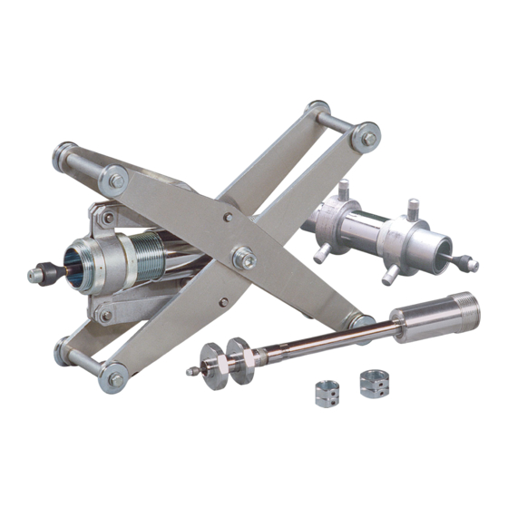
- Page 13 HBC-1 Centering Device HBC-2 Adjustable Carriage For 3" to 5" ID Pipe, Refer to Figure 8 For 5" to 12" ID Pipe, Refer to Figure 9 Item Description Stock No. Item Description Stock No. HBC-1 Collar and button set, complete ..01124 HBC-2 adjustable carriage, complete ..
Need help?
Do you have a question about the HOLLO-BLAST and is the answer not in the manual?
Questions and answers