Table of Contents
Advertisement
Quick Links
Permanent Magnet
ComNav Marine Ltd. #15-13511 Crestwood Place. Richmond, B.C. Canada. V6V-2G1
Telephone: 604-207-1600
Web: www.comnavmarine.com E-mail: sales@comnav.com
ComNav
Marine Ltd.
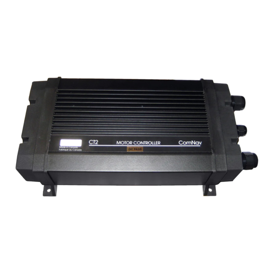
CT2-40A
MOTOR CONTROLLER
PART NUMBER 20350001
DOCUMENT PART NUMBER 29010024
Shunt Field Compound
Installation Instructions
Version 3.3
Facsimile: 604-207-8008
D.C. Motors
ComNav
Document PN 29010024
R
Advertisement
Table of Contents

Subscribe to Our Youtube Channel
Summary of Contents for Marine ComNav CT2-40A
- Page 1 PART NUMBER 20350001 DOCUMENT PART NUMBER 29010024 Permanent Magnet Shunt Field Compound D.C. Motors ComNav Installation Instructions Version 3.3 ComNav Marine Ltd. #15-13511 Crestwood Place. Richmond, B.C. Canada. V6V-2G1 Telephone: 604-207-1600 Facsimile: 604-207-8008 Web: www.comnavmarine.com E-mail: sales@comnav.com Document PN 29010024...
-
Page 2: Installation
Introduction: CT2-40A Motor Controllers are designed to connect a ComNav Autopilot to a steering system using a permanent magnet, shunt field, or compound reversing D.C. Motor. CT2-40A Motor Controllers feature dynamic braking, current limiting and thermal protection of the MOSFET driving transistors while allowing full power acceleration and drive when needed. CT2 Motor Controllers can be used with 12, 24 and 32 VDC battery systems. - Page 3 For the correct interconnection of the CT2 Motor Controller and the Autopilot refer to Figures 2 through 4. A four-conductor, #24 AWG cable with shield will be satisfactory. The shield of the cable should be terminated to the JOG COMMON terminal (or V-) in the Autopilot distribution box and unterminated at the other end.
-
Page 4: Troubleshooting
If it does run, the CT2 Motor Controller may be faulty. Contact your Dealer or ComNav Marine for assistance. If there is no voltage present the CT2 Motor Controller may be faulty. Contact your Dealer or ComNav Marine for assistance. -
Page 5: Electrical Noise
Check for nails or staples which may have penetrated the cable. If the diagnostic LED's do not come on, you may have a faulty Distribution Box or Control Head. Contact your Dealer or ComNav Marine for assistance. Electrical Noise: The CT2 Motor Controller uses high current switching transistors to control the motor. Every effort has been made to reduce or eliminate the generation of electrical noise by the motor controller. - Page 6 Figure 2 Connection to Permanent Magnet Motor Page 5 of 10 21/09/2007 29010024V3.3(2T Drive Box).doc...
- Page 7 Figure 3 Connection to Shunt Field Motor Page 6 of 10 21/09/2007 29010024V3.3(2T Drive Box).doc...
- Page 8 Figure 4 Connection to Compound Motor Page 7 of 10 21/09/2007 29010024V3.3(2T Drive Box).doc...
- Page 9 Figure 5 Connection to Processor Based Autopilots Page 8 of 10 21/09/2007 29010024V3.3(2T Drive Box).doc...
-
Page 10: Installation Steps
INSTALLATION STEPS: 1) Loosen six screws and remove the cover from the DU 1500 Servo unit to expose the PCB. 2) On the PCB, set DIP SWITCHES (S1-1) to UP to select Solenoid configuration. 3) Remove EndCaps and Enclosure from the CT2 box to expose the CT2 PCB. 4) On the PCB, shift the two-position shunt to between Pin1 and Pin2 of J3. - Page 11 INSTALLATION STEPS: 1) Loosen two screws and remove the cover from the DU 1510 Servo unit to expose the PCB. 2) On the PCB, set DIP SWITCHES (S1-1) to UP to select Solenoid configuration. 3) Remove EndCaps and Enclosure from CT2 box to expose the CT2 PCB. 4) On the PCB, shift the two-position shunt to between Pin1 and Pin2 of J3.
Need help?
Do you have a question about the ComNav CT2-40A and is the answer not in the manual?
Questions and answers