Table of Contents
Advertisement
Quick Links
Advertisement
Table of Contents

Related Manuals for HATO 400Y


Summary of Contents for HATO 400Y
- Page 1 AUTOMATION MANUAL FOR SLIDING GATES WITH SLOW DOWN...
-
Page 2: Recommendations And Precautions
Congratulations on your purchase of a sliding gate controller and welcome to the users of HATO products. Declarations of conformity and manuals for HATO POLSKA S.C. products can be downloaded from the website: http://www.hato.com.pl Before assembling and using the barrier for the first time, read the manual carefully and keep them for future reference. -
Page 3: Table Of Contents
Failure to follow the instructions above may result in serious injury or equipment damage. The manufacturer is not liable for damage and malfunctions resulting from failure to observe these installation and operating instructions. In accordance with the regulations in force on the disposal of waste equipment by private users in the European Union, items bearing this symbol MUST NOT be disposed of with other rubbish. -
Page 4: Important Safety Instructions
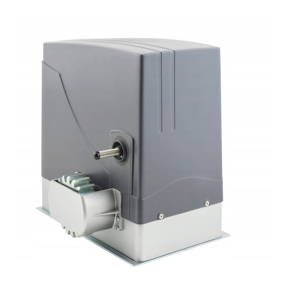
WARRANTY CONDITIONS..........................20 1. DESCRIPTION AND PRINCIPLE OF OPERATION OF THE DRIVE The HATO 400Y drive is designed for sliding gates. It has been equipped with an auto-reverse function, infrared sensors, partial opening (pedestrian crossing), mechanical unlocking enabling manual opening in the event of failure of the drive controller. - Page 5 3. MOUNTING OF THE LIMIT SWITCH CAMS Fig. 3.
-
Page 6: Description And Principle Of The Operation Of The Controller
Fig. 4 The cams of the limit switch should be mounted on the toothed rack bar. They should be pre- installed in such a way that the beginning of pressure on the limit switch is about 10 cm before the complete opening (closing) of the gate. -
Page 7: Driver Installation
• Simple installation and programming procedure. MODE OF ACTION The drive is controlled by the transmitter button programmed in HELB11 or the SBS sequence control bell button. In the case of control from the SBS input or a transmitter assigned to this function, the operation consists in carrying out the step-by-step commands OPEN-STOP- CLOSE-STOP or with the ONLY OPEN function enabled, it is only possible to open the gate. -
Page 8: Connection Of The Manual Control
necessary for the correct operation of the device and ensure safety. If the encoder support is disabled, it is required to connect a safety curtain or other additional protection against crushing in the gate's light. They must be connected in series with the photocells PHOTOCELL 12 +24VDC –... -
Page 9: Connection Diagram
The last stage of connection is to connect the controller power supply. Connect in turn the wires: 2 PE –protective conductor 3 L –phase wire 4 N –neutral wire Protect the controller power supply by using a residual current circuit breaker. -
Page 10: Setting Programming
SETTING PROGRAMMING Programming the controller is done using the SETUP, LEARN buttons, LED and ENCODER diodes and 4 function switches located on the controller board. Programming can only take place when the gate is in stop state. If we start programming the controller during the auto-closing time countdown, the countdown will be stopped and to close the gate, press the SBS button or the remote-control transmitter. -
Page 11: Autoclose Function
Hold the SETUP button again within 3 seconds. Pressing is signaled by continuous lighting of the diode. The LED will flash rapidly. Release the SETUP button. After releasing the button, the LED will show the current status of the function. The lighted on means the function is active, and the light off means the function is inactive. -
Page 12: Engine Operation Programming
Within 5s, start setting the time. Press SETUP x times. One press corresponds to 15s. Each pressing is signaled by the lighting of the diode. If the button is not pressed within these 5 seconds, the controller will set the default time. After 3s from the last press, the LED will flash 3 times. - Page 13 Press the SBS sequence control button for less than 3s or the transmitter button assigned to the SBS function. The gate will start to open (for work without an encoder with the power set on the P potentiometer). The LED will be on. To define deceleration positions before full opening, press the SBS sequential control button for less than 3 seconds or the transmitter button...
-
Page 14: Restoring Default Settings - 60S Operation Without Encoder And Without Deceleration
running in a given direction, do not press the SBS button and wait until the gate reaches its end position. ATTENTION! After each motor power adjustment on the VR1 ENGINE OPERATION PROGRAMMING potentiometer, the motor operation programming procedure must be repeated. For work with encoder support, adjust the overload with the potentiometer VR2, in accordance with the applicable standards. - Page 15 If the gate is in the fully closed position, the LED will flash quickly and items marked with asterisks * should be omitted. If the gate is not fully closed, the LED will flash slowly. Press the SBS sequence control button for less than 3s or the transmitter button assigned to the SBS function.
-
Page 16: Open Only Function
Release the SETUP button. If the gate is in the fully closed position, the LED will flash quickly, and if it is in another position, it will flash slowly. Hold down the SETUP button. The LED will blink 3 times. Release the SETUP button. -
Page 17: Photo Close Function
To disable the function, set the ONLY OP switch to the OFF position. PHOTO CLOSE FUNCTION Enables the gate to close faster and saves energy. During opening, after activation of the photocells, the gate will stop and with AUTO CLOSE enabled, after detecting a passage, the auto-closing time is shortened and the gate will close after 5 seconds. -
Page 18: Programming Of Transmitters
Release the button. When the diode stops blinking, the deletion procedure is finished and the controller will return to normal operation. PROGRAMMING OF TRANSMITTERS A maximum of 28 transmitters with a Keeloq dynamic code can be programmed. Each button must be learned separately. -
Page 19: Technical Specification
* the manufacturer reserves the right to change the remote control attached to the drive set DECLARATION OF CONFORMITY The HATO 400Y drive meets the requirements of the following regulations: Complies with the conditions of the Machinery Directive 2006/42 / EC Annex II Section B as amended. -
Page 20: Warranty Conditions
DEAR CUSTOMERS Thank you for purchasing a HATO product and congratulations on your choice. We guarantee the efficient operation of the device covered by this warranty in accordance with the technical and operating conditions described in the manual. At the same time, we would like to remind you that the installation carried out in accordance with the assembly instructions, proper use in accordance with the instructions for use and carrying out the obligatory maintenance inspections in accordance with the instructions, ensure trouble-free operation of the device. - Page 21 The buyer is obliged to notify the seller about the defect within 2 days from the date of its disclosure This warranty covers only HATO products installed and used in Poland An unfinished and / or non-stamped warranty card is invalid The warranty does not cover the costs of disassembly, reassembly and commissioning of the product as well as transport to the HATO service.
- Page 22 HATO POLSKA SP. Z O.O.
- Page 23 Tunelowa 57 40-676 Katowice POLAND tel. 032-785-25-42 www.hato.pl Magazyn i sprzedaż; ul. Żeromskiego 1 41-205 Sosnowiec DISTROBUTOR/SELLER...
Need help?
Do you have a question about the 400Y and is the answer not in the manual?
Questions and answers