
Related Manuals for Hemisphere GPS AtlasLink A326


Summary of Contents for Hemisphere GPS AtlasLink A326
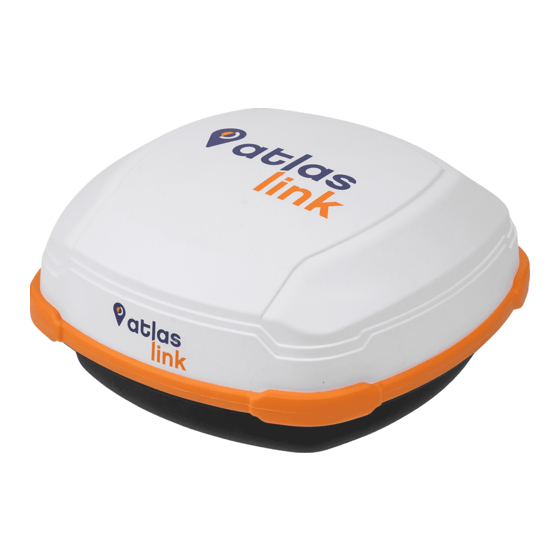
- Page 1 All manuals and user guides at all-guides.com ™ A326 AtlasLink Smart Antenna User Guide Part No. 875-0352-D Rev. A4...
- Page 2 All manuals and user guides at all-guides.com This device complies with part 15 of the FCC Rules. Operation is subject to the following two conditions: (1) This device may not cause harmful interference,and (2) this device must accept any interference received, including interference that may cause undesired operation.
-
Page 3: Table Of Contents
All manuals and user guides at all-guides.com Contents Contents Chapter 1: Introducing AtlasLink Smart ................. 1 Antenna ......................... 1 AtlasLink Overview..................2 Key Features ..................... 3 Parts List ....................3 Product Support ..................3 Chapter 2: Installing AtlasLink ..................4 Display, Mounting, and Connector ............ - Page 4 All manuals and user guides at all-guides.com Contents Chapter 3: Troubleshooting ..................33 Chapter 4: Technical Specifications ................36 Warranty Notice ..................43 AtlasLink Quick Reference Guide PN 875-0352-D Rev A4...
-
Page 5: Chapter 1: Introducing Atlaslink Smart
All manuals and user guides at all-guides.com Chapter 1: Introducing AtlasLink Smart Antenna Chapter 1: Introducing AtlasLink Smart Antenna AtlasLink Overview Key Features Parts List Product Support AtlasLink User Guide PN 875-0352-D Rev A4... -
Page 6: Atlaslink Overview
All manuals and user guides at all-guides.com Chapter 1: Introducing AtlasLink Smart Antenna AtlasLink Overview Hemisphere GNSS’ all-new AtlasLink multi-GNSS, multi-frequency smart antenna is preconfigured to receive corrections from Atlas GNSS global correction service. *AtlasLink was designed from the ground up to excel in challenging environments and is ideal for use in a variety of applications including precision agriculture, machine control, construction, mining, and marine Automotive only for Korea. -
Page 7: Key Features
All manuals and user guides at all-guides.com Chapter 1: Introducing AtlasLink Smart Antenna Key Features Key features of AtlasLink include: • Centimeter-level accuracy using Atlas* or Athena** technology in a rugged, all-in-one enclosure *requires subscription **requires activation • Improved GNSS performance—particularly with RTK and/or L-Band applications •... -
Page 8: Chapter 2: Installing Atlaslink
All manuals and user guides at all-guides.com Chapter 2: Installing AtlasLink Chapter 2: Installing AtlasLink Display, Mounting, and Connector LED Display Mounting AtlasLink Selecting the Proper Antenna Location Routing and Securing the Cables Mounting Options Powering AtlasLink Connecting to AtlasLink Web UI AtlasLink User Guide PN 875-0352-D Rev A4... -
Page 9: Display, Mounting, And Connector
All manuals and user guides at all-guides.com Chapter 2: Installing AtlasLink Display, Mounting, and Connector All connections and ports are located on the bottom of the unit, as shown in Figure 2-1. Table 2-1 provides additional information about each port/connection. Mounting holes Power/data... -
Page 10: Mounting Atlaslink
All manuals and user guides at all-guides.com Chapter 2: Installing AtlasLink Mounting AtlasLink This section provides information on where to mount your antenna and the different mounting options available. Selecting the Proper Antenna Location Proper antenna placement is critical to positioning accuracy. To select the proper antenna location: •... -
Page 11: Surface Mount
All manuals and user guides at all-guides.com Chapter 2: Installing AtlasLink Surface Mount You can surface-mount AtlasLink with four machine screws (no. 8-32). Bottom To surface-mount AtlasLink: Determine the desired location for AtlasLink (see “Selecting the Proper Antenna Location” on page 7). A template of the bottom portion of the AtlasLink surface-mount has been provided to you within the included AtlasLink accessories. -
Page 12: Pole Mount
All manuals and user guides at all-guides.com Chapter 2: Installing AtlasLink Pole Mount The center thread on the bottom of AtlasLink is 1.” The mounting assembly included with AtlasLink includes an 5/8” adapter compatible with common survey poles. Simply thread the riser/pole into the antenna until snug. -
Page 13: Powering Atlaslink
All manuals and user guides at all-guides.com Chapter 2: Installing AtlasLink Powering AtlasLink Power Considerations AtlasLink accepts an input voltage of 7-32 VDC. For best performance use a clean and continuous power supply. When applying 12 VDC, AtlasLink will draws approximately 4.9 W. -
Page 14: Power/Data Connector
All manuals and user guides at all-guides.com Chapter 2: Installing AtlasLink Power/Data Connector Figure 2-1 shows the 12-pin power/data connector pin-out assignment and Table 2-2 provides the pin-out specifications. Note: The Wire Color column in Table 2-2 refers to the color of the wires at the unterminated end of accessory item 051-0169-000 (4.6 m unterminated power/data cable). -
Page 15: Connecting To Atlaslink Web Ui
All manuals and user guides at all-guides.com Chapter 2: Installing AtlasLink Connecting to AtlasLink Web UI In order to access the AtlasLink smart antenna’s web UI, you must connect to its WiFi access point using a computer, tablet, or phone. By default, the access point will be named “atlaslink_########” where ######## is replaced by the ESN (Electronic Serial Number) of your unit. -
Page 16: Atlaslink Web Ui Pages
All manuals and user guides at all-guides.com Chapter 2: Installing AtlasLink AtlasLink Web UI Pages From the Main Menu pictured above, you can access the various pages of the user interface. On each page you can click the “Home” button in the top-right corner to return to the main menu, or use the usual back/forward navigation in your web browser. -
Page 17: Status - Receiver Information
All manuals and user guides at all-guides.com Chapter 2: Installing AtlasLink Status Pages Status - Receiver Information The Receiver Information page can be accessed from the “RX Info” subheading of the main menu, under “Status”. This page shows some general information about the GNSS receiver such as serial number, firmware versions, how long the smart antenna has been running, and subscription information. -
Page 18: Status - Position
All manuals and user guides at all-guides.com Chapter 2: Installing AtlasLink Status – Position The Position Information page can be accessed from the “Position” subheading of the main menu, under “Status”. This page shows the smart antenna’s current position as well as other information such as the accuracy, solution type, and age of differential. -
Page 19: Status - Tracking
All manuals and user guides at all-guides.com Chapter 2: Installing AtlasLink Status – Tracking The Tracking page can be accessed from the “Tracking” subheading of the main menu, under “Status.” This page shows a summary of all the satellites currently being tracked, in both the form of a sky plot (the circles represent 0, 30, and 60 degree elevations) and a table showing the signal strength of each signal. -
Page 20: Status - L-Band/Sbas
All manuals and user guides at all-guides.com Chapter 2: Installing AtlasLink Status – L-Band/SBAS The L-Band/SBAS Status page can be accessed from the “L-Band/SBAS” subheading of the main menu, under “Status”. This page shows diagnostic information about the tracking of the Atlas L-Band or SBAS signal. Please avoid setting the frequency or baud rate without ensuring you have the correct information. -
Page 21: Receiver Mode Pages
All manuals and user guides at all-guides.com Chapter 2: Installing AtlasLink Receiver Mode Pages The receiver mode can be changed via the main menu, by selecting the radio button to the left of the desired mode. When you’ve changed the selected mode, a “Change Mode” button will appear as shown below. The mode of the receiver will change once the user confirms the new selection by clicking this button. -
Page 22: Receiver Mode - Rover
All manuals and user guides at all-guides.com Chapter 2: Installing AtlasLink Receiver Mode – Rover The Rover Configuration page can be accessed from the “Rover” subheading of the main menu, under “Receiver Mode”. The “Maximum Differential Age” option controls the number of seconds after which the receiver will stop using a differential source once corrections are no longer being received. -
Page 23: Receiver Mode - Baselink
All manuals and user guides at all-guides.com Chapter 2: Installing AtlasLink Receiver Mode – BaseLink The BaseLink configuration page can be accessed from the “BaseLink” subheading of the main menu, under “Receiver Mode.” The BaseLink receiver mode is where you can configure the receiver to start outputting RTK base station corrections data via a serial port, once a specified reference station position accuracy has been reached using Atlas corrections. - Page 24 All manuals and user guides at all-guides.com Chapter 2: Installing AtlasLink In order to use BaseLink, configure the correction output format and baud rate desired, the target accuracy level (in 3D 2-sigma), and click the “Save” button. The receiver will then begin to show information below the form indicating the current BaseLink status.
-
Page 25: Receiver Mode - Smartlink
All manuals and user guides at all-guides.com Chapter 2: Installing AtlasLink Receiver Mode – SmartLink The SmartLink configuration page can be accessed from the “SmartLink” subheading of the main menu, under “Receiver Mode.” The SmartLink receiver mode allows another GNSS receiver capable of using external open-standard corrections to benefit from the Atlas correction service. - Page 26 All manuals and user guides at all-guides.com Chapter 2: Installing AtlasLink In order to use SmartLink, configure the correction output format and baud rate desired, the target accuracy level (in 2D 1-sigma), and click the “Save” button. The receiver will then begin to show information below the form indicating the current SmartLink status.
-
Page 27: Configuration Pages
All manuals and user guides at all-guides.com Chapter 2: Installing AtlasLink Configuration Pages Configuration – Device Name The Device Name configuration page can be accessed from the “Device Name” subheading of the main menu, under “Configuration”. This menu is used to rename the device. The customized device name can be shown on the heading at the top of the web UI. -
Page 28: Configuration - General
All manuals and user guides at all-guides.com Chapter 2: Installing AtlasLink Configuration – General The General Configuration page can be accessed from the “General” subheading of the main menu, under “Configuration.” This page is used for configuring GNSS receiver settings which apply to all modes. AtlasLink User Guide PN 875-0352-D Rev A4... -
Page 29: Configuration - Wifi
All manuals and user guides at all-guides.com Chapter 2: Installing AtlasLink Configuration – WiFi The WiFi Configuration page can accessed from the “WiFi” subheading of the main menu under “Configuration”. This configuration page is used to change the setting for the smart antenna’s WiFi support. From this menu the access point’s name, and security settings can be changed. -
Page 30: Configuration - Logging
All manuals and user guides at all-guides.com Chapter 2: Installing AtlasLink Configuration – Logging The Logging Configuration page can be accessed from the “Logging” subheading of the main menu under “Configuration”. This page can be used to configure the AtlasLink smart antenna’s built-in data-logging support. - Page 31 All manuals and user guides at all-guides.com Chapter 2: Installing AtlasLink The Observations option specifies whether the binary messages for observations will be logged, and at what rate. The Ephemeris option specifies whether satellite ephemeris binary messages are logged. The Corrections option specifies whether messages containing correction information (i.e. Atlas, RTK, SBAS) will be logged.
-
Page 32: Filesystem
All manuals and user guides at all-guides.com Chapter 2: Installing AtlasLink Filesystem The Filesystem menu can be accessed from the “Filesystem” heading of the main menu. From this menu you can access log files from the logging system, and also upload firmware updates to the device. -
Page 33: Firmware Update
All manuals and user guides at all-guides.com Chapter 2: Installing AtlasLink Firmware Update As indicated in the above section, firmware update capability can be accessed by going to the “Filesystem” page and uploading new firmware to the device. When loading GNSS firmware, after uploading the file, click the “Load GNSS FW” button to begin the process, after which you should see a series of pages like the following: AtlasLink User Guide PN 875-0352-D Rev A4... - Page 34 All manuals and user guides at all-guides.com Chapter 2: Installing AtlasLink Once the Firmware Update page looks like the last page shown above, the GNSS firmware update process is complete. When upgrading the carrier board firmware, after uploading the file click the “Update Carrier FW” link to begin the process, after which you should see a series of pages like the following.
-
Page 35: Reboot
All manuals and user guides at all-guides.com Chapter 2: Installing AtlasLink Reboot The web browser will remain at the “Reboot” page shown above until the device you are using to view the web UI reestablishes communication with the AtlasLink smart antenna, after which you will be sent directly to the main menu. - Page 36 All manuals and user guides at all-guides.com Chapter 3: Troubleshooting Chapter 3: Troubleshooting AtlasLink User Guide PN 875-0352-D Rev A4...
- Page 37 All manuals and user guides at all-guides.com Chapter 3: Troubleshooting Table 3-1 provides a list of issues with possible solutions to help you troubleshoot anomalous AtlasLink operation. Table 3-1: Troubleshooting Issue Possible Solution Receiver fails to power • Verify polarity of power leads •...
- Page 38 All manuals and user guides at all-guides.com Chapter 3: Troubleshooting Table 3-1: Troubleshooting (continued) Issue Possible Solution • Power-cycle the receiver AtlasLink LED displays solid color (not blinking) • Contact Technical Support (See page ii for contact information) • Check firewalls on your device Not able to connect to AtlasLink via WiFi •...
- Page 39 All manuals and user guides at all-guides.com Chapter 4: Technical Specifications Chapter 4: Technical Specifications AtlasLink User Guide PN 875-0352-D Rev A4...
- Page 40 All manuals and user guides at all-guides.com Chapter 4: Technical Specifications Table 4-1 through Table 4-7 provide the GNSS sensor, horizontal accuracy, L-Band sensor, communication, power, environmental, and mechanical specifications for the AtlasLink. Table 4-1: GNSS sensor specifications Item Specification Receiver type GNSS L1 &...
- Page 41 All manuals and user guides at all-guides.com Chapter 4: Technical Specifications Table 4-4: Communication specifications (continued) Item Specification Baud rates 4800 - 115200 Data I/O protocol NMEA 0183, NMEA 2000*, Hemisphere GNSS binary, *requires NMEA certification Bluetooth Yes. Bluetooth 2.0 (Class 2) Wi-Fi Web UI Yes.
- Page 42 All manuals and user guides at all-guides.com Chapter 4: Technical Specifications Table 4-7: Mechanical specifications (continued) Item Specification Weight <1.15 kg (<2.53 lbs) Status indicators (LED) • Blinking Red - Power on • Blinking Amber - GNSS position available, includingRTK float and Atlas •...
- Page 43 All manuals and user guides at all-guides.com End User License Agreement IMPORTANT - This is an agreement (the "Agreement") between you, the end purchaser (“Licensee”) and Hemisphere GNSS Inc. (“Hemisphere”) which permits Licensee to use the Hemisphere software (the “Software”) that accompanies this Agreement. This Software may be licensed on a standalone basis or may be embedded in a Product.
- Page 44 All manuals and user guides at all-guides.com potential positioning and navigation accuracy obtainable with the Software as stated in the Product or Software documentation serves to provide only an estimate of achievable accuracy based on specifications provided by the US Department of Defense for GNSS positioning and DGNSS service provider performance specifications, where applicable.
- Page 45 All manuals and user guides at all-guides.com TERMINATION. Licensee may terminate this Agreement at any time without cause. Hemisphere may terminate this Agreement on 30 days notice to Licensee if Licensee fails to materially comply with each provision of this Agreement unless such default is cured within the 30 days.
- Page 46 All manuals and user guides at all-guides.com Warranty Notice COVERED PRODUCTS: This warranty covers all products manufactured by Hemisphere GNSS and purchased by the end purchaser (the “Products”), unless otherwise specifically and expressly agreed in writing by Hemisphere GNSS. LIMITED WARRANTY: Hemisphere GNSS warrants solely to the end purchaser of the Products, subject to the exclusions and procedures set forth below, that the Products sold to such end purchaser and its internal components shall be free, under normal use and maintenance, from defects in materials, and workmanship and will substantially conform to Hemisphere GNSS's applicable specifications for the Product, for a period of 12 months from delivery of such Product to such end purchaser (the ”Warranty Period”).
- Page 47 All manuals and user guides at all-guides.com Hemisphere ® Hemisphere GNSS, Inc. 8515 Anderson Drive Scottsdale, AZ 85255, USA Phone: +1 (480) 348-6380 Fax: +1 (480) 270-5070 Precision@HGNSS.com www.HGNSS.com...
- Page 48 All manuals and user guides at all-guides.com...
Need help?
Do you have a question about the AtlasLink A326 and is the answer not in the manual?
Questions and answers