Table of Contents

Related Manuals for Link 2600

Summary of Contents for Link 2600
- Page 1 System 2600 Programmable Limit Switch and Die Protection Installation and Operating Manual Doc # L-2600-1023 Rev. 02 Link Electric & Safety Control Co. 444 McNally Drive Nashville, TN 37211 Phone: (615) 833-4168 Fax: (615) 834-1984 © 2020...
-
Page 3: Table Of Contents
Counters ............................. 49 3.5.1 Configuring Production Counters ..................50 3.5.2 Production Counters......................50 3.5.3 Cycle Counter ........................52 The Diagnose Screen ........................53 3.6.1 Ethernet Diagnostics ......................53 3.6.2 SD Card Diagnostics ......................54 Doc #: L-2600-1023 Page 1 Rev. 02... - Page 4 Store Setup ..........................70 Recall Setup..........................71 Erase Setup ..........................71 Data Storage ..........................72 New Die Installation........................72 BACKING UP AND RESTORING THE SYSTEM 2600............... 73 Backup Procedure ........................73 Restore Procedure ........................74 Memory Swap-out Procedure..................... 76 INSTALLATION ..........................77 Preliminary Installation Considerations ..................
- Page 5 Wiring the RUN (Clutch/Brake) Input ................87 7.5.5 Wiring the 5100-11 Rotary Transducer ................88 7.5.6 Wiring the Auxiliary Inputs ....................89 7.5.7 Wiring the Die Protection Inputs ..................89 7.5.8 Wiring Optional Limit Switch Modules ................91 Doc #: L-2600-1023 Page 3 Rev. 02...
- Page 6 Table of Figures Figure 1: System 2600 ..........................6 Figure 2: System 2600 ..........................10 Figure 3: Top Info Area with 5100-11 Encoder..................11 Figure 4: Example Numeric Entry Screen ....................13 Figure 5: Example Text Entry........................13 Figure 6: Example List Selection ......................14 Figure 7: Example Password Entry Sequence ..................
- Page 7 Figure 74: 805-3 Comm. Board Mounting ....................83 Figure 75: General View of Wiring Runs for Installation ................ 85 Figure 76: 2600-2 Board Connections ...................... 86 Figure 77: Breakaway of Run/Stop Connector ..................87 Figure 78: 5100-11 Encoder Connections ....................88 Figure 79: Auxiliary Inputs Connection for Setup Mode .................
-
Page 8: Introduction
Once configured, these settings will be automatically recalled with each job. The System 2600 can be programmed to monitor each individual die protection input in the manner necessary to ensure that the process is operating in the intended manner. Each channel can be programmed to function as one of several logic types, which are covered in the configuration section. -
Page 9: Features
• If bypassing of the entire unit is needed or desired, a setting is available that will automatically un-bypass it when switching back to a production mode. Doc #: L-2600-1023 Page 7 Rev. 02... -
Page 10: Specifications
PLS angles, and so on are entered directly in degrees and require no external cam switches. • The Clutch/Brake signal of the press can be monitored by the 2600 to detect problems with the coupling of the encoder to the crankshaft such as a broken chain. -
Page 11: Definitions And Terminology
If the control determines that it cannot stop at top in the time left when it receives the stop command, it will typically make an additional stroke. Many high speed presses take more than 1 full stroke to stop regardless of where the stop occurs. Doc #: L-2600-1023 Page 9 Rev. 02... -
Page 12: Operation
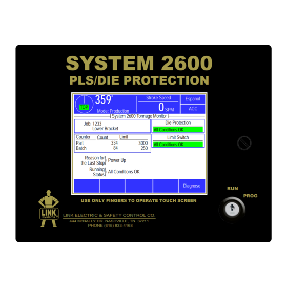
Status Diagnose PROG USE ONLY FINGERS TO OPERATE TOUCH SCREEN LINK ELECTRIC & SAFETY CONTROL CO. 444 McNALLY DR. NASHVILLE, TN. 37211 PHONE (615) 833-4168 Figure 2: System 2600 Areas inside the white portion of the display are shown with a blue border if that area can be selected. -
Page 13: Figure 3: Top Info Area With 5100-11 Encoder
When stopped within +/- 5 degrees of bottom, “BOT” will appear in a yellow background. Note that for certain presses (such as link drives) “Top” may not be at 0 degrees. c) Numeric Display... -
Page 14: Acc Softkey
3.1.3 RUN/PROG (Run/Program) Switch This is a keyed selector switch read directly by the System 2600. The PROG (program) position causes the unit to assert a Top Stop, and prevents machine initiation until the switch is returned to the RUN position. -
Page 15: Figure 4: Example Numeric Entry Screen
The Numbers & Misc softkey will then change to Upper Case. Pressing Upper Case brings the virtual keyboard back to its original configuration with upper case letters. Doc #: L-2600-1023 Page 13 Rev. 02... -
Page 16: Configuration Code
There are four possible modes of operation for the restricted access system. They are the “Key Only” mode, the “Key or Password” mode, the “Password Only” mode, and the “Key and Password” mode. The control can be configured to operate in any one of these four modes. Doc #: L-2600-1023 Page 14 Rev. 02... - Page 17 The setup personnel must be assigned a user name and password. In addition, all restricted items would be assigned access to the setup personnel. Doc #: L-2600-1023 Page 15 Rev. 02...
-
Page 18: Access Control Operation
3.1.8.1 RUN/PROG Key Switch Operation The RUN/PROG key switch is located on the lower right side of the System 2600. This is a two- position switch. The key is removable in the RUN position only. If the RUN/PROG key switch is being used as a means to access the restricted items, the switch must be turned to the PROG position. -
Page 19: Figure 7: Example Password Entry Sequence
Step D: Upon entry of the correct password, the user will be allowed access to the restricted item. In this example, the user will be allowed to change the Auto Single Stroke Time parameter from the 10 sec setting that was previously programmed. Doc #: L-2600-1023 Page 17 Rev. 02... - Page 20 10 strokes, the user will be logged out when the press completes 10 strokes after the last key stroke. If the user presses a key before 10 strokes have been completed, a new 10 stroke cycle will be started. Doc #: L-2600-1023 Page 18 Rev. 02...
-
Page 21: Restricted Items
The following table lists the different items and functions in the unit that can be configured to be restricted. See section 4.11.4 for details on how to set up restrictions. System 2600 Restricted Items/Functions Name Function... - Page 22 Bypass the die protection system DP Limited Bypass Limited bypass of the die protection system Feed Settings Change feed settings though the servo feed interface Special Interface Change settings in certain other optional interfaces Doc #: L-2600-1023 Page 20 Rev. 02...
-
Page 23: Main Operator Terminal Screen
NOTE: The press control for the machine will have other stop sources besides the System 2600 (E-Stop buttons, light curtains, etc.) that can stop the press without the System 2600 knowing why. When this happens the “Reason for the Last Stop” will show External Stop. Stops initiated by the System 2600 (such as from counters, die protection channels, etc.) will display... -
Page 24: Running Status
If no stop condition exists, then the message All Conditions OK indicates the System 2600 is not asserting its stop outputs. The “Running Status” message will indicate where the operator needs to go to take corrective action (reset a counter, clear a die protection fault, etc.). -
Page 25: Die Protection
Die Protection The System 2600 features 6 built-in die protection channels which are designed for use in monitoring various material and tool conditions that are important to the correct operation of the process. This is accomplished by installing appropriate sensors and probes in or near the die and connecting these sensors to the die protection channel inputs of the operator terminal. -
Page 26: Figure 9: Static Normally Off Example
This allows the operator to avoid nuisance faults from sensors that 'bounce' open or closed momentarily. The delay time can range from 0 to 65535 milliseconds (65.535 seconds) in 1 millisecond increments. Doc #: L-2600-1023 Page 24 Rev. 02... -
Page 27: Figure 11: Cyclic Input Example
The center unacceptable figure shows that event did occur, but did so outside the timing window. The right unacceptable figure shows that the event did not turn off during an entire press stroke. All three of these situations are fault conditions. Doc #: L-2600-1023 Page 25 Rev. 02... -
Page 28: Figure 13: "In Position" Input Example
“Window On” and “Window Off” points for a timing window during which the material will move into place. The “Window On” angle must be set to a point before the material gets into position. The Doc #: L-2600-1023 Page 26... -
Page 29: Figure 14: Timing Window Examples For An "In Position" Input
– which will then cause a stop in the downstroke. Also see section 4.2.5 on page 56 for more information on how inhibit behaves and the considerations for its use. Doc #: L-2600-1023 Page 27 Rev. 02... -
Page 30: Figure 15: "1 Part Detector Edge" Input Example
“On” when the part is in the sensor. When a “Normally On” sensor is being used to sense part out; the sensor will be “On” when the part is not in the sensor, and will be “Off” when the part is in the sensor. Doc #: L-2600-1023 Page 28 Rev. 02... -
Page 31: Figure 17: "1 Part Detector Pass" Input Example
“On” when the part is in the sensor. When a “Normally On” sensor is being used to sense part out; the sensor will be “On” when the part is not in the sensor, and will be “Off” when the part is in the sensor. Doc #: L-2600-1023 Page 29 Rev. 02... -
Page 32: Figure 19: "2 Part Detector Edge" Input Example
“On” when the part is in the sensor. When a “Normally On” sensor is being used to sense part out; the sensor will be “On” when the part is not in the sensor, and will be “Off” when the part is in the sensor. Doc #: L-2600-1023 Page 30 Rev. 02... -
Page 33: Figure 21: "2 Part Detector Pass" Input Example
“On” when the part is in the sensor. When a “Normally On” sensor is being used to sense part out; the sensor will be “On” when the part is not in the sensor, and will be “Off” when the part is in the sensor. Doc #: L-2600-1023 Page 31 Rev. 02... -
Page 34: Figure 23: Timing Window Example For A "Transfer" Input
This type uses the “Separation Time” parameter to prevent false multiple counts from thin and/or tumbling parts. After a part is detected, a new part will not count until the separation time has passed. Doc #: L-2600-1023 Page 32 Rev. 02... -
Page 35: The Die Protection Main Screen
(shown by “a” in Figure 24). c) Detailed Info This area shows information on the particular settings that apply to the channel type. This varies from type to type. Doc #: L-2600-1023 Page 33 Rev. 02... - Page 36 Reset Softkey This softkey is used to reset die protection fault conditions. Note that some errors, primarily those generated from “Static” inputs, may not clear until some action is corrected in the die. Doc #: L-2600-1023 Page 34 Rev. 02...
-
Page 37: Die Protection Channel Settings Main Screen
(0 to 359 degrees). This could be displayed as more than one arc if the sensor turns “On” in multiple places in the stroke. The captured sensor angles are automatically updated every stroke. Doc #: L-2600-1023 Page 35 Rev. 02... - Page 38 Anywhere Section 3.3.1.10 on page 32 for more information about this type. Note that this type is only available for selection when one or more counters have been configured for sensor- based counting. Doc #: L-2600-1023 Page 36 Rev. 02...
- Page 39 24 volts when “On” should use this input type. For instance, a mechanical limit switch that is tied between 24 volts and the input would use a “Sensor Type” of “PNP (Source)”. Doc #: L-2600-1023 Page 37 Rev. 02...
-
Page 40: Die Protection Channel Miscellaneous Settings Screen
“Immediate Stop” and “Top Stop”. See Section 2.1 on page 9 for details on these stop types. The user must select a stop type appropriate for the process. Doc #: L-2600-1023 Page 38 Rev. 02... - Page 41 “Separation Time”. The range of allowed values for the separation time is 0 milliseconds to 9999 milliseconds in 1 millisecond increments. The proper value for a particular application will have to be determined by experimentation. Doc #: L-2600-1023 Page 39 Rev. 02...
-
Page 42: Die Protection Channel Window Angles Setting Screen
System Bypass softkey. Press this softkey to Feed Complete bypass all the sensors on the die protection system Part Detector Exit – this effectively turns die protection off. Figure 30: Die Protection Bypass Screen Doc #: L-2600-1023 Page 40 Rev. 02... - Page 43 - assuming that a system bypass or limited bypass is not in effect. To automatically bypass a sensor in a setup mode, set the parameter in the “Bypass In Setup Mode” column for the Doc #: L-2600-1023 Page 41...
-
Page 44: Die Protection Diagnose Screen
This can range from the current stroke (0 degrees to the current angle) to as many as about 20 strokes back. The exact number of strokes back that can be viewed is dependent on the number of transitions that have occurred per stroke. The system stores the last 64 on/off transitions. Doc #: L-2600-1023 Page 42 Rev. 02... - Page 45 The Overlay Strokes softkey will cause all stored capture data from all strokes to be displayed on the angle display. This allows the user to view sensor variation in order to choose the timing window more reliably. Doc #: L-2600-1023 Page 43 Rev. 02...
-
Page 46: Limit Switch
Limit Switch The System 2600 can optionally support up to 8 programmable limit switch outputs. 3.4.1 Limit Switch Main Screen If installed, touching the Limit Switch area of the Stroke Speed Espanol main operator screen (see Figure 8 on page 21) will bring up the screen shown in Figure 32. - Page 47 When the channel is in “Normal”, “Timed Off”, or “Toggle” mode, the channel can be speed advanced. Press inside the blue bordered angle area (see “c” in Figure 33) and the speed advance settings screen will be shown (see Section ). Doc #: L-2600-1023 Page 45 Rev. 02...
-
Page 48: Limit Switch Counted Output Settings Screen
0. The count can be changed, if needed, to set the output to fire in a particular number of strokes or to synchronize the output will another channel that was also a counted output. Doc #: L-2600-1023 Page 46 Rev. 02... -
Page 49: Limit Switch Angle And Time Setting Screen
“On” after it passes the “On Angle”. The up and down arrow keys to the right of the parameters can be used to increment or decrement the value without going into the numeric editing screen. Doc #: L-2600-1023 Page 47 Rev. 02... -
Page 50: Limit Switch Speed Advance Settings Screen
Lead Time The “Lead Time” is the mechanical reaction time when the limit switch turns on. 3.4.5.3 Trail Time The trail time is the mechanical reaction time when the limit switch turns off. Doc #: L-2600-1023 Page 48 Rev. 02... -
Page 51: Counters
Limit State On / 3600 10000 Reset Part The System 2600 can support 1 or 2 counter groups. A counter group includes a part counter, a On / Trip Reset Batch batch (or bin) counter, and a scrap counter. The... -
Page 52: Configuring Production Counters
3.5.2 Production Counters The three production counters provided are Part, Batch and Quality. All production counters that are turned “On” will increment as the press strokes. Doc #: L-2600-1023 Page 50 Rev. 02... - Page 53 The scrap counter can be set, incremented, and decremented manually. If the Inc. Scrap key is pressed, then 1 is added to the scrap count and 1 is subtracted from the part and bin counters. Likewise, if the Doc #: L-2600-1023 Page 51...
-
Page 54: Cycle Counter
3.5.3 Cycle Counter The cycle counter increments anytime the crankshaft travels from the top of the stroke to the bottom of the stroke. Contact Link Systems service department to reset the cycle counter. Doc #: L-2600-1023 Page 52... -
Page 55: The Diagnose Screen
Top Stop Relay – Shows the On/Off status of the top stop relay. Note that “On” indicates the System 2600 is NOT asserting a top stop. Immediate Stop Relay – Shows the On/Off status of the immediate stop relay. Note that “On” indicates the System 2600 is NOT asserting an immediate stop. -
Page 56: Sd Card Diagnostics
3.6.4 Event Log The System 2600 retains an event log which can be displayed by pressing the Event Log softkey in the screen of Figure 40. This log records the reason for the last 256 stops. All reasons for last stop that are generated by the System 2600 are recorded. -
Page 57: Configuration
CONFIGURATION The Main Configuration Screen Stroke Speed The configuration screens of the System 2600 are Espanol accessed by selecting the Configure System softkey Mode: Production in the main screen (see Figure 8 on page21) with Configure System the RUN/PROG keyed selector switch in the... -
Page 58: Setup Mode Input
By setting this parameter to “No”, inhibit conditions will not drop out the Top Stop relay. An output relay module can be added to the System 2600 that has a separate output for inhibit conditions. If supported by the press control, it can be tied into the control in such a way as to avoid resetting the press control on every stroke while preventing stroking if asserted. -
Page 59: Encoder Settings Configuration Screen
5.0 degrees is normally a reasonable value and this should only be changed if instructed by Link technicians. RUN (Clutch/Brake) Input Settings Configuration Screen... -
Page 60: Engagement Time Limit
1.2. For example, if the longest actual engagement time is 100 milliseconds, enter a value of 120 milliseconds (100 X 1.2 = 120) for the “Engagement Time Limit”. Doc #: L-2600-1023 Page 58 Rev. 02... -
Page 61: Motion Threshold
If these occur, you may increase the time calculated by the formula but, in no case should this time be increased more than 2.5 times the value calculated by the formula. Doc #: L-2600-1023 Page 59 Rev. 02... -
Page 62: Bypass Settings Configuration Screen
The automatic unbypass feature only removes the bypass when the press mode changes from setup mode to production mode. Once in a production mode, any user who has been granted access to do so can again select a bypass. Doc #: L-2600-1023 Page 60 Rev. 02... -
Page 63: Editing The Die Protection Name List
Figure 51: Edit Limit Switch Names Screen NOTE: If a particular limit switch name is changed in this screen, then all jobs with limit switch channels set to that description will show the new description in its place. Doc #: L-2600-1023 Page 61 Rev. 02... -
Page 64: Restricting And Unrestricting Die Protection Channels
These channels can not be Protection changed in settings screens and are not affected by job affected by job recalls. recalls. Module: 2600 DP/PLS Press the Restrict / Unrestrict Die Protection softkey Channel Type Description Restricted... -
Page 65: Output Relays Configuration
“Not Installed” or “Installed”. Since Output Relays are optional, depending on application, none or all modules may be installed for a given press. When selected to “Installed”, the System 2600 will Stroke Speed Espanol... - Page 66 Turn On if Crank in Motion Type 9 Turn On if Run/Prog Switch in Prog, Off in Run Type 10 Turn On if Unit is powered Type 11 Turn On if LinkNet Down Time Code is Active Doc #: L-2600-1023 Page 64 Rev. 02...
-
Page 67: Operator Terminal Configuration
The “Rod Length” is the length of the connection between the center of the crankshaft and the slide connection point. The “Stroke Length” is the total linear travel of the press slide from top to bottom. Doc #: L-2600-1023 Page 65 Rev. 02... -
Page 68: Setting The Date And Time
4.11.4.1 Access Mode Configuration There are four access modes. These are “Key and Code”, “Code Only”, ” Key or Code”, and “Key Only”. These modes are explained in section 3.1.7 on page 14. Doc #: L-2600-1023 Page 66 Rev. 02... -
Page 69: Figure 59: User Access Configuration Screen
(“Used” set to “Yes”), the user’s name will appear on a list of possible users that may obtain access control. When a user is disabled (“Used” set to “No”), the user’s name will not appear on a list of possible users that may obtain access control. Doc #: L-2600-1023 Page 67 Rev. 02... -
Page 70: Figure 60: Restrict/Unrestrict Screen
Limit Switch Setting, Names and Messages, Counter Configuration, Tonnage Monitor Make sure you record and keep this code in a secure place. If it lost, you will have to contact Link Systems Configuration, Die Protection Configuration, and to restore access to the configuration screens. -
Page 71: Configure Auxiliary Communications
These options include serial communication ports for interfacing to auxiliary equipment (such as PLCs), a laptop interface for downloading messages, and a network interface. See the manual pertaining to the particular device that is connected for communication. Doc #: L-2600-1023 Page 69 Rev. 02... -
Page 72: Job Setups
Press the Store Setup softkey in order to save the current job information in the internal file system under the job number and job description displayed. The operator terminal automatically returns to the Job Setups screen. Doc #: L-2600-1023 Page 70 Rev. 02... -
Page 73: Recall Setup
Job Recall screen does (with Erase Selected and Erase By Job Num. softkeys). The operator terminal will ask for confirmation from the user before actually erasing the job. Doc #: L-2600-1023 Page 71 Rev. 02... -
Page 74: Data Storage
All settings are stored on the Micro-SD card located on the circuit board in the door of the unit. If necessary, the 2600-2 board (the board in the bottom of the enclosure) can be swapped between units and will still receive the proper settings for that press. -
Page 75: Backing Up And Restoring The System 2600
6 BACKING UP AND RESTORING THE SYSTEM 2600 The System 2600 stores its settings in its internal storage. This section is intended to give maintenance personnel the necessary procedures to back up and restore the memory to a secure digital card. Backups that are created can be used to restore the settings stored in the backup to the same unit, or to a different unit in cases where the original unit must be replaced due to damage. -
Page 76: Restore Procedure
Backups made from the same unit show up in the main backup / restore screen. The user entered description is shown along with the date and time that the backup was made. To restore a backup file to the same unit that made it: Doc #: L-2600-1023 Page 74 Rev. 02... - Page 77 Do not remove power from the unit until the operation is finished. • Press the Exit softkey and the operator terminal will reboot with the new settings. Doc #: L-2600-1023 Page 75 Rev. 02...
-
Page 78: Memory Swap-Out Procedure
There will usually be a tactile “click” when the connector is seated properly. After the Micro-SD card is installed, power up the new unit and verify that the settings are correct. Doc #: L-2600-1023 Page 76 Rev. 02... -
Page 79: Installation
Preliminary Installation Considerations The System 2600 comes in its own enclosure that should be located close to the machine control for easy access, keeping in mind that the operator will need to interact with the screen from time to time. -
Page 80: Mounting The System 2600
Mounting the System 2600 The System 2600 comes in an enclosure ready to bolt on to the machine. Display Surface Consideration should be given to the viewing angle of the operating personnel. Figure 67 shows the most usable viewing angles for the LCD display used in the Link OIT - about 30 degrees “above”... -
Page 81: Figure 69: Enclosure Dimensions
7.25” are in millimeters (184) 6.75” 8” (171) (203) PROG 0.31” (7.9) Door diameter Opens (4 places) Door Hinge 7/8 Knockouts (5 places) 4.6” (117) 2” (51) 8.5” (216) Figure 69: Enclosure Dimensions Doc #: L-2600-1023 Page 79 Rev. 02... -
Page 82: Mounting The Encoder
Mounting the Encoder The System 2600 requires a Link Resolver or 5100-11 encoder to get angle Encoder information from the crankshaft or Chain or eccentric. Timing Belt Press The encoder may be direct driven by a coupling off the center of the shaft or... -
Page 83: Figure 72: 5100-11 Encoder Dimensions
(43.2) (25.8) Allow 3.0” (76) clearance for 1.50” (38.1) mating connector Shaft 0.75” (19.1) 0.75” (19.1) 5.9” (149.0) diameter Circular ZERO Connector 2.50” 1.50” SIDE (63.5) (38.1) 1.37”(34.8) Figure 72: 5100-11 Encoder Dimensions Doc #: L-2600-1023 Page 81 Rev. 02... -
Page 84: Figure 73: Spring Base With 5100-11 Encoder Dimensions
(88.9) 3.75” 3.25” (95.3) (82.6) 4.0” (102) 4.3” 100% Compressed 0% Compressed (109.2) 50% Compressed 50% Compressed 4.5” (114.3) 0% Compressed 100% Compressed 4.65” (118.1) Figure 73: Spring Base with 5100-11 Encoder Dimensions Doc #: L-2600-1023 Page 82 Rev. 02... -
Page 85: Installing The 805-3 Communications Card
Installing the 805-3 Communications Card The optional 805-3 communications board mounts on ISO GND the circuit board in the door of the System 2600 as shown in Figure 74. Carefully mate it to the matching connector on the 1200-1 ETHERNET 805-3 Comm. -
Page 86: System Wiring
System Wiring 7.5.1 Conduit Runs Wiring for the System 2600 should generally be run in conduit. The use of flexible liquid tight conduit with ground is suggested, but hard conduit can also be used. Figure 75 shows some of the typical conduit runs that may be required. -
Page 87: Figure 75: General View Of Wiring Runs For Installation
115VAC conduit with from press ground for control any optional transformer low voltage to power connections: Sensor setup mode Interface input etc. PROG Figure 75: General View of Wiring Runs for Installation Doc #: L-2600-1023 Page 85 Rev. 02... -
Page 88: Wiring Power For The System
Arc Flash compliance. Pull wires with the appropriate color code in conduit between the System 2600 enclosure and the press control. Remember to run high voltage wiring in one conduit and low voltage wiring in a separate conduit. -
Page 89: Wiring The Stop Outputs
7.5.4 Wiring the RUN (Clutch/Brake) Input In the case of Mechanical Presses, the System 2600 can optionally use a signal from the press clutch/brake control that indicates when the press clutch is engaged (the press is stroking). This signal is derived from the voltage across the dual air valve solenoid (in some cases a hydraulic valve may be used) that controls stroking and may be 24VDC or 120VAC. -
Page 90: Wiring The 5100-11 Rotary Transducer
Figure 77. On the System 2600 end, the wires must be connected to terminals 5 and 6 of the “Run / Stop Connector” (See Figure 76 to locate this connector). -
Page 91: Wiring The Auxiliary Inputs
Figure 80. This example is showing a NPN part +24V sensor powered using the internal power supply of the System 2600. Figure 80: Die Protection Inputs Connection Wiring Example with Internal Power Supply Likewise, mechanical switch sensors or spring probes would simply ground the input if was set to NPN mode, or connect it to +24V if it was set to PNP mode. -
Page 92: Figure 81: Die Protection Inputs Connection Wiring Example With External Power Supply
Figure 81 shows how an external power supply can be connected for additional sensor power. Diffuse Reflective Part Sensor Also note that if the System 2600 itself (NPN) is powered by +24VDC instead of 120VAC, then it can pass along 1 amp POWER SUPPLY to sensors. -
Page 93: Wiring Optional Limit Switch Modules
Figure 83: Electro-Mechanical Limit Switch Module modules Figure 84 shows how to connect limit switch modules to the System 2600. The special double plugs on the limit switch modules allow simple daisy chaining of the wiring from the System 2600 to the first module, and then to the second and third modules, if used. -
Page 94: Figure 85: Limit Switch Outputs
Solid State DC Relay 60 VDC Max, 3 Amps @ 45º ambient, 2 Amps @ 70º ambient Relay Contact Fuse (all relay Littlefuse 0251007 (7 Amp, 125V AC or DC, Fast Blow) types) Doc #: L-2600-1023 Page 92 Rev. 02...
Need help?
Do you have a question about the 2600 and is the answer not in the manual?
Questions and answers