Sign In
Upload
Manuals
Brands
Link Manuals
Switch
2600
Link 2600 Manuals
Manuals and User Guides for Link 2600. We have
1
Link 2600 manual available for free PDF download: Installation And Operating Manual
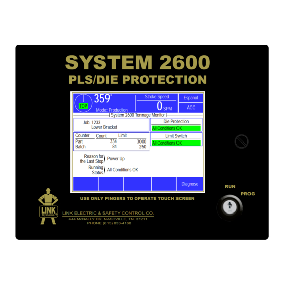
Link 2600 Installation And Operating Manual (94 pages)
Programmable Limit Switch and Die Protection
Brand:
Link
| Category:
Switch
| Size: 1 MB
Table of Contents
Table of Contents
3
1 Introduction
8
Figure 1: System 2600
8
Features
9
Specifications
10
2 Definitions and Terminology
11
Stops
11
Immediate Stop
11
Top Stop
11
3 Operation
12
Operator Interface
12
Figure 2: System 2600
12
Figure 3: Top Info Area with 5100-11 Encoder
13
ACC Softkey
14
Automatic LCD Turn off
14
Espanol/English Softkey
14
Parameter Entry
14
RUN/PROG (Run/Program) Switch
14
Figure 4: Example Numeric Entry Screen
15
Figure 5: Example Text Entry
15
Access Control Modes
16
Configuration Code
16
Figure 6: Example List Selection
16
Access Control Operation
18
Figure 7: Example Password Entry Sequence
19
Restricted Items
21
Unrestricted Items
21
Main Operator Terminal Screen
23
Reason for the Last Stop
23
Figure 8: Operator Terminal Main Screen
23
Running Status
24
Configure Softkey
24
Diagnose Softkey
24
Toggle Setup Mode
24
Die Protection
25
Die Protection Channel Types
25
Figure 9: Static Normally off Example
26
Figure 10: Static Normally on Example
26
Figure 11: Cyclic Input Example
27
Figure 12: Timing Window Examples for a Cyclic Input
27
Figure 13: "In Position" Input Example
28
Figure 14: Timing Window Examples for an "In Position" Input
29
Figure 15: "1 Part Detector Edge" Input Example
30
Figure 16: Timing Window Example for a "1 Part Detector Edge" Input
30
Figure 17: "1 Part Detector Pass" Input Example
31
Figure 18: Timing Window Example for a "1 Part Detector Pass" Input
31
Figure 19: "2 Part Detector Edge" Input Example
32
Figure 20: Timing Window Example for a "2 Part Detector Edge" Input
32
Figure 21: "2 Part Detector Pass" Input Example
33
Figure 22: Timing Window Example for a "2 Part Detector Pass" Input
33
Figure 23: Timing Window Example for a "Transfer" Input
34
The die Protection Main Screen
35
Figure 24: die Protection Main Screen
35
Die Protection Channel Settings Main Screen
37
Figure 25: die Protection Main Screen with Error
37
Figure 26: die Protection Channel Settings Screen
37
Die Protection Channel Miscellaneous Settings Screen
40
Figure 27: Wiring Sensors in Series and Parallel
40
Figure 28: die Protection Channel Misc. Settings Screen
40
Die Protection Channel Window Angles Setting Screen
42
Die Protection Bypass Screen
42
Figure 29: die Protection Channel Angle Setting Screen
42
Figure 30: die Protection Bypass Screen
42
Die Protection Diagnose Screen
44
Figure 31: die Protection Diagnose Screen
44
Limit Switch
46
Limit Switch Main Screen
46
Limit Switch Settings Screen
46
Figure 32: Limit Switch Main Screen
46
Figure 33: Limit Switch Settings Screen
46
Limit Switch Counted Output Settings Screen
48
Figure 34: Limit Switch Counted Output Screen
48
Limit Switch Angle and Time Setting Screen
49
Figure 35: Limit Switch Angle and Time Setting Screen
49
Limit Switch Speed Advance Settings Screen
50
Figure 36: Limit Switch Speed Advance Screen
50
Counters
51
Figure 37: Counter Screen
51
Figure 38: Counter Group Screen
51
Configuring Production Counters
52
Figure 39: Counter Configuration Screen
52
Production Counters
52
Cycle Counter
54
The Diagnose Screen
55
Ethernet Diagnostics
55
Figure 40: Main Diagnostic Screen
55
SD Card Diagnostics
56
OIT Info Screen
56
Event Log
56
Figure 41: Event Log Screen
56
Figure 42: Event Log Detail Information Screen
56
4 Configuration
57
The Main Configuration Screen
57
The General Settings Configuration Screen
57
Allow Speed Advanced Outputs
57
Machine Running Timeout
57
Figure 43: Main Configuration Screen
57
Figure 44: General Settings Configuration Screen
57
Setup Mode Input
58
Log External Stops
58
Inhibit Asserts Top Stop
58
Top of Stroke Angle
58
Encoder Settings Configuration Screen
59
Trigger Mode
59
Encoder Offset
59
Encoder Reversed
59
Crankshaft Hysteresis
59
RUN (Clutch/Brake) Input Settings Configuration Screen
59
Figure 45: Encoder Settings Screen
59
Figure 46: RUN Input Settings Screen
59
Engagement Time Limit
60
Figure 47: Clutch Engagement Time
60
Figure 48: Loss of Motion Time and Motion Threshold
61
Loss of Motion Time
61
Motion Threshold
61
Bypass Settings Configuration Screen
62
Limited Bypass Maximum Strokes and Maximum Time
62
System Bypass Allowed
62
Auto Unbypass When Switching to Production Mode
62
Figure 49: Bypass Settings Configuration Screen
62
Editing the die Protection Name List
63
Editing the Limit Switch Name List
63
Figure 50: Edit die Protection Names Screen
63
Figure 51: Edit Limit Switch Names Screen
63
Restricting and Unrestricting die Protection Channels
64
Restricting and Unrestricting Limit Switch Channels
64
Figure 52: Restrict/Unrestrict die Protection Screen
64
Figure 53: Restrict/Unrestrict Limit Switch Screen
64
Output Relays Configuration
65
Figure 54: Output Relays Configuration Screen
65
Figure 55: Output Relays Function Configuration Screen
65
Operator Terminal Configuration
67
Top Area Display
67
Rod Length and Stroke Length
67
Figure 56: Operator Terminal Configuration Screen
67
Setting the Date and Time
68
Access Configuration
68
Figure 57: Date and Time Setting Screen
68
Figure 58: Access Configuration Screen
68
Figure 59: User Access Configuration Screen
69
Figure 60: Restrict/Unrestrict Screen
70
Figure 61: Set Config Code Screen
70
Configure Auxiliary Communications
71
5 Job Setups
72
Store Setup
72
Figure 62 Jobs Screen
72
Figure 63 Store Jobs Screen
72
Recall Setup
73
Erase Setup
73
Figure 64 Recall Jobs Screen
73
Data Storage
74
New die Installation
74
6 Backing up and Restoring the System 2600
75
Backup Procedure
75
Figure 65: SD Card Location
75
Restore Procedure
76
Memory Swap-Out Procedure
78
Figure 66: SD Card Location
78
7 Installation
79
Preliminary Installation Considerations
79
Mounting the System 2600
80
Figure 67: OIT Viewing Angles
80
Figure 68: Enclosure Dimensions Side View with Shock Mounts
80
Figure 69: Enclosure Dimensions
81
Mounting the Encoder
82
Figure 70: Resolver Mounting to Shaft
82
Figure 71: Encoder on Spring Base
82
Figure 72: 5100-11 Encoder Dimensions
83
Figure 73: Spring Base with 5100-11 Encoder Dimensions
84
Installing the 805-3 Communications Card
85
Figure 74: 805-3 Comm. Board Mounting
85
System Wiring
86
Conduit Runs
86
Figure 75: General View of Wiring Runs for Installation
87
Wiring Power for the System
88
Figure 76: 2600-2 Board Connections
88
Wiring the Stop Outputs
89
Wiring the RUN (Clutch/Brake) Input
89
Figure 77: Breakaway of Run/Stop Connector
89
Wiring the 5100-11 Rotary Transducer
90
Figure 78: 5100-11 Encoder Connections
90
Wiring the Auxiliary Inputs
91
Wiring the die Protection Inputs
91
Figure 79: Auxiliary Inputs Connection for Setup Mode
91
Figure 80: die Protection Inputs Connection Wiring Example with Internal Power Supply
91
Figure 81: die Protection Inputs Connection Wiring Example with External Power Supply
92
Figure 82: Model 2620 Sensor Interface
92
Wiring Optional Limit Switch Modules
93
Figure 83: Electro-Mechanical Limit Switch Module
93
Figure 84: Limit Switch Module Wiring
93
Figure 85: Limit Switch Outputs
94
Advertisement
Advertisement
Related Products
Link E-Fax 2P
Link 2620
Link SW4X1-4KUHD
Link Categories
Automobile Accessories
Extender
Matrix Switcher
Control Unit
Media Converter
More Link Manuals
Login
Sign In
OR
Sign in with Facebook
Sign in with Google
Upload manual
Upload from disk
Upload from URL