Table of Contents
Advertisement
Advertisement
Table of Contents

Related Manuals for OTOLIFT 87


Summary of Contents for OTOLIFT 87
- Page 1 Otolift type 87 Functionality & troubleshooting Date 221209...
-
Page 2: Table Of Contents
Manual TYPE 87 Table of content Page-number 1. Chairlift in general 1.1 Basics 1.2 Need-to-know locations on the PCB 1.3 Names and locations 1.4 Definition left/right 1.5 Software version 2. Functionality and connections 2.1 Controls 2.2 Safety inputs 2.3 Sensitive edges safety inputs 2.4 Other inputs... -
Page 3: Type
7. Remotes / transmitters and receivers 7.1 Programming the 2-channel remotes into the 2-channel receiver 7.2 Reverse logic up/down of 2 channel remote 7.3 Adjusting the dipswitches of the 1-channel transmitter and receiver 16 7.4 Types and type numbers 8. Powered hinge 8.1 Powered sliding hinge 8.2 Powered folding hinge 8.3 Warning for older type of PCB’s... -
Page 4: Chairlift In General
1. Chairlift in general 1.1 Basics - Closed loop control for controlling the synchronous motor and DC brake. - On board charging-circuit for charging the batteries (= 2x12V/7Ah) - The lift is equipped with a buzzer on the PCB and a LED in the armrest for failure report to the user. - The PCB has a display for failure report to the mechanic or installer. -
Page 5: Names And Locations
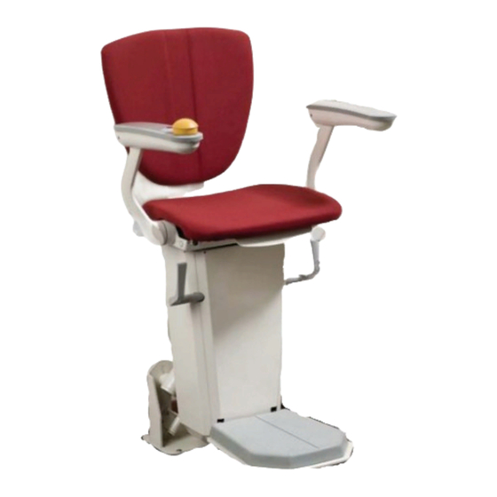
1.3 Names and locations Control armrest (switch Swivelseat switch left-right) Armrest-switch incl. LED Overspeed governor (catch) & rotation monitor unit Safety drive-unit Receiver(s) Endswitch Charging contact Safety switch chairframe Safety switch bottom of chairframe Safety switches footrest 1.4 Definition left/right When the left or right side of the chair is mentioned, it is always seen from the position of the user when he or she is seated on the chairlift. -
Page 6: Functionality And Connections
2. Functionality and connections 2.1 Controls If one of these controls is activated, and the safety contacts are not operated, the chairlift will start to move in the controlled direction. Control input connected to connector-name Control armrest right (NO) X2a- Arm1 Control armrest left (NO) -
Page 7: Other Inputs
Sensitive edges safety inputs left side If one of these safety devices are controlled, the lift can not move in the left direction. It is still possible for the lift to move in the right direction. Control input connected to connector-name Endswitch left (NC) -
Page 8: Outputs
2.4 Outputs Supply output +/-24Vdc 1 4A current limited 22~29V output, for powering the powered sliding hinge. Through charge-points. (wiring connected to x10 -2,3 Supply output +/-24Vdc 2 22~29V output for powering the powered folding hinge board. Max 2A (externally fused) (wiring connected to x11 -1,2 Logic switched output 1 If the lift has reached an endpoint and has stopped, this output... -
Page 9: Dipswitches On The Pcb
3. Dipswitches on the circuit board The dipswitches on the circuit board have their own logic functions. Dipswitch 1= on => The rotation monitor unit is monitored on its functionality. If the rotation monitor (RMU) does not give an alternating signal, during 30 cm of moving the lift, the lift stops. -
Page 10: Programming The Chairlift
4. Programming the chairlift 4.1 Need to know before programming The chairlift must always be programmed, when moving to the right. (seen from user position) Thus a lift which is mounted on the left side of the stairs, must be programmed from the endpoint at the top till the endpoint of the bottom, and a lift which is mounted on the right side of the stairs, must be programmed from endpoint of the bottom till the endpoint at the top. -
Page 11: Programming The Chairlift
4.2 Programming the chairlift Only start programming the lift, when the lift is operating OK (without bypass-connector.) The hinge should stand in the hinge out position. Keep the transformer connected to the mains-voltage Start programming procedure when ‘potentiometer’ speed is set. Programming procedure: Switch on Service. -
Page 12: Bypass-Connectors And Interconnections
The bypass connector also overrides the overspeed governor safety-contact. (Catch) 5.2 Interconnections on the PCB Some connectors are not used in the type 87 application. In this case we use jumpers to make the interconnection. X3b is standard interconnected by a jumper. -
Page 13: Charging The Batteries
Because of this we can charge more accurate, which results in a longer lifetime of the batteries. The maximum charge-current is 1,1A . The transformer of the type 87 is NOT a battery-charger. You can not and may not use this transformer for charging batteries directly. -
Page 14: Battery-Fuse
6.4 Battery-fuse For protection of all electronics a main-fuse is put in series with the batteries. The fuse-holder is placed as an interconnection between the batteries In case of standard 130 kg lift a 20A blade fuse is needed. 6.5 Sleepmode When the lift has not been charged for 1 or 8 hours it will go into a sleepmode. - Page 15 7. Remotes/transmitters and receivers. The chairlift has a separated receiver (PCB) built in for remote-control. In case of a powered sliding hinge 2 extra remotes and 1 receiver is used for controlling the hinge in and out. Also an extra 1-channel transmitter (on the hinge) and 1-channel receiver (in the chairlift) is applied for hinge-is-down command.
- Page 16 7.3 Adjusting the dipswitches of the 1-channel transmitter and receiver To make the 1-channel receiver work with the 1-channel transmitter you have to adjust the dipswitches of both in the same way. Dipswitches 1-channel receiver 1-channel transmitter The receiver and transmitter always have the same dipswitch settings, when they come from the manufacturer.
- Page 17 8. Powered hinge At this moment we have 2 different powered hinges. The powered sliding hinge needs less space then the powered folding hinge when folded in. 8.1 Powered sliding hinge The powered sliding hinge uses extra remote-controls for moving the hinge up/down. A 1-channel transmitter and receiver are used for ‘hinge is down’-command.
- Page 18 8.3 Warning for older type of hinge PCB’s. Some of the older type hinge PCB’s are not compatible to the type 87, and some of type 87 parts are not backward-compatible to older types of lifts. PCB’s which you can/ may use in combination with the 86900 PCB and transformer are;...
- Page 19 9. Error-handling for mechanic 9.1 Diagnostic display A display on the PCB shows the actual error. More detail info of this display errors is attached to this document. (attachment 87900 error eng). The display can show the following errors. S w itc h in a rm re s t is in o ff p o s itio n S w itc h in a rm re s t is o n (m a in s a fe ty -lin e O K ) S w iv e ls e a t-s w itc h is o p e ra te d E x tra c o n ta c t is n o t in te rc o n n e c te d (b y ju m p e rs , 1 -c h a n n e l re c e iv e r o r s s p 0 0 8 v 3 a n d /o r S E N S O R )
- Page 20 9.2 LED’s on the PCB There are 4 LED’s mounted on the PCB. The 3 LED’s left bellow are mounted for indication of the status of the 375 mA SMD fuse, contact of overspeed governor (catch) and limitswitch/jumper. (LED 1, 2 & 3) The LED near the display shows the status of the PCB.
- Page 21 Example 2 There was a problem, but the user is not able to inform you. When you read the error log you see the following errors. 5 2 _ _ 5 _ 5_ F _ _ 6 7 _ _ 0 _ _ 0 F- Display-error 5 means that the lift was controlled on 2 locations at the same time.
- Page 22 9.5 fuse safety-line A 375 mA SMD fuse is used as a safety-fuse for all the switches in the safetyline. The fuse melts when a wire or contact from the safety-line has a short-circuit to (chassis) ground. When the fuse is broken the display shows 8888y, the 3 LED’s at the left bottom are off, and the LED near the display should be on.
- Page 23 9.8 Working description Over speed Governor (OSG) Type 87 When the over speed governor is installed on the lift, dipswitch 1 needs to be in on position. (If the dipswitch is off and the Count hammer moves, the lift will give ERROR P in the display.) Working description: The Drive wheel is friction driven and rotates when the lift moves over the rail.
- Page 24 9.9 Working description folding rail The folding rail PCB (ssp 008v3) in the chair has a set/reset memory, Current consumption (ca 60 mA) gives a reset. A pulse from the folding rail PCB (ssp 007v3) sets the memory. The red led on the PCB is on when the memory is set.(chair switched on) The orange LED goes off when there is a current-consumption.
- Page 25 9.10 Working description proximity switch (sensor) All Chairlifts with a flat backward curve with a radius of 315 mm will have an inductive proximity switch in the counter pressure unit. The inductive proximity switch is added to the chair to prevent damages. Without the inductive proximity switch the toothed wheel can damage the rail when it hits the rail.
- Page 26 10. Error-handling for the user of the chairlift 10.1 Operating the chairlift The chairlift will not start to move directly when operated , it will start to drive after 1 second of operating. Before start to drive a 0,5 second beep will be heard. (start-to-move-signal) When the chairlift is stopped on a endpoint a 0,25 second beep will be heard.
- Page 27 10.3 Logic of the beeper When the LED in the armrest is on and the chairlift will not move when controlled, the beeper will be heard 1 second after releasing the control. In this case one of the sensitive edges is controlled The number of beeps gives the location of the controlled sensitive edge.
- Page 28 Attachments 86900 PCB eng => drawing of lay-out PCB and info 86900 S1 eng => schematics main PCB 86900 86900 CW1 eng => connection of wiring, page 1 86900 CW2 eng => connection of wiring, page 2 86900 SS eng =>...
- Page 32 Type 86 Type 87...
Need help?
Do you have a question about the 87 and is the answer not in the manual?
Questions and answers