Table of Contents
Advertisement
Quick Links
1.
2.
GENERAL INFORMATION
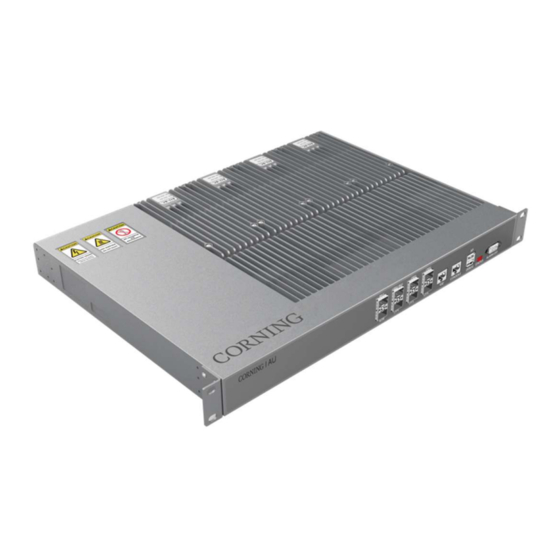
The E62-M2RU is a medium-power remote unit supporting cellular technologies on fiber optic
cable using the CPRI protocol. The M2 is ideal for multioperator multiband deployments of
cellular services in medium-to-large coverage areas. The M2 supports up to 37 dBm output
per band in single 4T4R or dual 2T2R up to 100 MHz per band. The M2 converts an optical
signal to RF and then transmits at the relevant 3GPP band and receives the analog RF signal,
conditions it, and converts it back to optical for routing to the E2 or A2.
This document describes the installation procedure for the E62-M2 unit.
This is NOT a CONSUMER device. It is designed for installation by FCC LICENSEES and
QUALIFIED INSTALLERS. You MUST have an FCC LICENSE or express consent of an FCC
License to operate this device. NOTE: Only authorized person can enter the area where the
antenna is installed. And the person is fully aware of the potential for exposure and can exercise
control over his or her exposure by leaving the area or by some other appropriate means.
Awareness of the potential for RF exposure in a workplace or similar environment can be provided
through specific training as part of a RF safety program.
Mid-Power (E62-M2)
Installation Manual
Everon™ 6200
Installation Manual | CMA-795-AEN | Page 1
Advertisement
Table of Contents

Subscribe to Our Youtube Channel
Related Manuals for CORNING Mid-Power E62-M2RU


Summary of Contents for CORNING Mid-Power E62-M2RU
- Page 1 Mid-Power (E62-M2) Installation Manual Everon™ 6200 GENERAL INFORMATION The E62-M2RU is a medium-power remote unit supporting cellular technologies on fiber optic cable using the CPRI protocol. The M2 is ideal for multioperator multiband deployments of cellular services in medium-to-large coverage areas. The M2 supports up to 37 dBm output per band in single 4T4R or dual 2T2R up to 100 MHz per band.
-
Page 2: Table Of Contents
Content Preface ............................... 4 Safety Instructions ..........................4 Site Considerations ..........................6 Environmental Considerations ......................6 DC Power Connections ........................7 Warning Marks........................... 8 Unpacking and Inspecting ......................... 9 Inspecting the Packing Container ....................9 Unpacking the Device........................9 Verifying the Contents ........................9 Inspecting the Device ........................ - Page 3 Accessories List ..........................32 Wall Installation (Back on the Wall) ..................... 33 Wall Installation (Side on the Wall) ...................... 39 Pole Installation ..........................44 M2RU Mounting Dimension Spacing ....................45 Optical Connection ........................... 46 Optical Transceiver Module ......................46 Single Port Bidirectional SFP Transceiver ..................46 Dual Port SFP Transceiver ......................
-
Page 4: Preface
Preface Safety Instructions All the following “Safety Precautions” must be observed during the entire installation and operation of the Everon™ 6200 system. The Everon™ 6200 system components are designed for maximum safety and reliability when they are installed, used, and maintained by trained and qualified technicians in accordance with the procedures and instructions contained in this manual. - Page 5 RF exposure requirements. 17. In accordance with wireless service provider standards it is not advised to use digital repeaters as a signal source for Corning solutions. 18. Antenna gain should not exceed 6 dBi.
-
Page 6: Site Considerations
Site Considerations Everon™ 6200 complies with FCC RF exposure limits for an uncontrolled environment. The system delay should be taken into consideration when there are neighboring BTS sites that are overlapping in coverage. Normal use of the system will not damage the base station; however, with the increase of RU during network coverage for indoor distribution, the uplink output noise level may affect the sensitivity of the base station, which should be considered during engineering design. -
Page 7: Dc Power Connections
DC Power Connections Referring to the diagram, connect the power cables as follows: Higher voltage wire linked to cable / Lower voltage wire linked to BLUE cable. Connect “+” to a high potential (+48 VDC from a +48 VDC power supply; 0 VDC from a -48 VDC power supply) ... -
Page 8: Warning Marks
Warning Marks The warning marks on the Everon™ 6200 shell should be kept clean, readable, and identifiable. ALWAYS disconnect all lines and power connections before servicing or disassembling this equipment. NEVER touch the surface after the device's power is turned on. For performance and safety reasons, NEVER disassemble and remodel the devices. -
Page 9: Unpacking And Inspecting
Do not open or unpack the container. Immediately contact the transportation carrier and notify them of the damage. File a claim with the carrier once you determine the extent of any damage. Return it to CORNING’s nearest RMA facility and contact CORNING for RMA processing. -
Page 10: Inspecting The Device
Inspecting the Device After unpacking the device, place the device on solid ground and check the following to ensure the device has not been damaged: Inspect the device’s appearance, overall dimensions, and weight. Check that the device has not been deformed or bent in any way. Check that there are no warps, scratches, bubbles, or dirt marks. -
Page 11: Tools
Tools Electric drill, crosshead screwdriver, side cutters, ladder, and other tools are needed for M2RU installation. Customers are to provide these tools themselves. Drilling Machine Allen Wrench T5 Combination Nut M10 and Spanner 17 mm Installation Manual | CMA-795-AEN | Page 11... -
Page 12: Installing The Access Unit (Au)
Installing the Access Unit (AU) Accessories List Installation Manual | CMA-795-AEN | Page 12... -
Page 13: Rack Installation
Rack Installation The Access Unit is a 19-inch 1U equipment shelf. When installing the Access Unit in a rack, make sure the mechanical loading of the rack is even to avoid a hazardous condition. The rack should safely support the combined weight of all the equipment and be securely anchored. - Page 14 Place the AU in the rack and secure the AU using 2 screws M6×16 on both side and the Phillips screwdriver. Install the cooling fan if multiple AUs are installed in the same rack. It is necessary to allow at least 3 rack units (132 mm) of free space below each unit for heat dissipation without fan installed or 1 rack unit (44 mm) of free space below each unit with fan occupied in the middle.
- Page 15 Connect and lock the power cable at the AU rear side. Connect and screw the ground wire at the AU rear side. Installation Manual | CMA-795-AEN | Page 15...
-
Page 16: Fan Installation
Fan Installation 1. Secure the fan using 2 screws M6×16 on both sides and the Phillips screwdriver 2. Plug AC power lead. Installation Manual | CMA-795-AEN | Page 16... - Page 17 3. Fan DC version has power cable embedded in chassis. Note: Red is for positive; black is for negative. There are labels at cable ends to distinguish positive or negative pole. Note: Connect “+” to a high potential (+48 VDC from a +48 VDC power supply; 0 VDC from a -48 VDC power supply) Note: Connect “-”...
-
Page 18: Wall Installation
Wall Installation To install the Access Unit on the wall: Rotate the handles 90°and attach them at the rear of the AU, using 4 screws M3×6 per bracket and the Phillips screwdriver. Observe the orientation of the brackets. Installation Manual | CMA-795-AEN | Page 18... - Page 19 Mark 4 x ∅6.8 mm drilling holes sites for the hanger to be attached to the wall. Drill 4 holes at the marked sites using percussion drill and embed 4×10 plastic expansion pipes. Note: H = 70 mm. Fasten the case with 4×M6 expansion bolt.
- Page 20 Connect and lock the power cable at the AU rear side Connect and screw the ground wire at the AU rear side Installation Manual | CMA-795-AEN | Page 20...
-
Page 21: Au Mounting Dimension Spacing
AU Mounting Dimension Spacing Installation Manual | CMA-795-AEN | Page 21... -
Page 22: Rf Connection
RF Connection The RF interface between the Access Unit and the service provider signal source (or Everon™ 6200 CPOI) is provided by duplex connections on the Active Combiner module. To route and connect the coaxial cables to the Access Unit: Obtain the required lengths of high-performance, flexible, low-loss 50Ω... -
Page 23: Installing The Expansion Unit (Eu-O)
Installing the Expansion Unit (EU-O) Accessories List Installation Manual | CMA-795-AEN | Page 23... -
Page 24: Rack Installation
Rack Installation The Expansion Unit is a 19-inch 1U equipment shelf. When installing the Access Unit in a rack, make sure the mechanical loading of the rack is even to avoid a hazardous condition. The rack should safely support the combined weight of all the equipment and be securely anchored. - Page 25 Place the EU in the rack and secure the EU using 2 screws M6×16 on both side and the Phillips screwdriver. Installation Manual | CMA-795-AEN | Page 25...
- Page 26 Reserve enough free space or install the fan for cooling if multiple devices are installed in the same rack. It is necessary to allow at least 2 rack units (88 mm) of free space below each unit for heat dissipation without fan installed or 1 rack unit (44 mm) of free space below each unit with fan occupied in the middle.
- Page 27 Connect and lock the power cable at the EU rear side. Connect and screw the ground wire at the EU rear side. Installation Manual | CMA-795-AEN | Page 27...
-
Page 28: Wall Installation
Wall Installation To install the Expansion Unit on the wall: Rotate the handles 90° and attach them at the rear of the EU, using 4 M3×6 screws per bracket and the Phillips screwdriver. Observe the orientation of the brackets. Installation Manual | CMA-795-AEN | Page 28... - Page 29 Mark 4 x ∅6.8 mm drilling holes sites for the hanger to be attached to the wall Drill 4 holes at the marked sites using percussion drill and embed 4×∅10 plastic expansion pipes. Note: H = 70 mm. Fasten the case with 4×M6 expansion bolt. Installation Manual | CMA-795-AEN | Page 29...
- Page 30 Connect and lock the power cable at the AU rear side Connect and screw the ground wire at the AU rear side Installation Manual | CMA-795-AEN | Page 30...
-
Page 31: Eu-O Mounting Dimension Spacing
EU-O Mounting Dimension Spacing Installation Manual | CMA-795-AEN | Page 31... -
Page 32: Installing The Mid Power Remote Unit (M2Ru)
Installing the Mid-Power Remote Unit (M2RU) Accessories List Installation Manual | CMA-795-AEN | Page 32... -
Page 33: Wall Installation (Back On The Wall)
Wall Installation (Back on the Wall) Attach and fasten the handle to the side of M2RU with screws M6×14 using T5 Wrench. Attach and fasten the Bracket I to the back of M2RU with screws M6×14 using T5 Wrench. Installation Manual | CMA-795-AEN | Page 33... - Page 34 Mark the position of the drilling holes in the mounting Bracket II. Note: R = 13 mm. Drill 4 holes at the marked positions. Note: H = 70 mm Installation Manual | CMA-795-AEN | Page 34...
- Page 35 Attach the dowels, expansion screws or the like, and fasten the Bracket II to the wall. Tip: Use Bracket II as a reference to control each devices’ separation distance before hanging and locking M2RU up. Hang the M2RU on the mounting Bracket II and fasten with nuts M10. Installation Manual | CMA-795-AEN | Page 35...
- Page 36 Installation Manual | CMA-795-AEN | Page 36...
- Page 37 Fasten the Bracket I and II with screws M6×14. Connect and lock the power cable at the M2RU rear side Installation Manual | CMA-795-AEN | Page 37...
- Page 38 Connect and screw the ground cable at the M2RU’s left side Installation Manual | CMA-795-AEN | Page 38...
-
Page 39: Wall Installation (Side On The Wall)
Wall Installation (Side on the Wall) Attach and fasten the handle to the side of M2RU with screws M6×14 using T5 Wrench. Figure 1. Installation Manual | CMA-795-AEN | Page 39... - Page 40 Attach and fasten the Bracket I to the left side of M2RU with screws M6×14 using T5 Wrench. Mark the position of the drilling holes in the mounting Bracket II. Note: R = 13 mm. Installation Manual | CMA-795-AEN | Page 40...
- Page 41 Drill 4 holes at the marked positions. Note: H = 70 mm. Attach the dowels, expansion screws or the like and fasten the Bracket II to the wall. Tip: Use Bracket II as a reference to control each devices’ separation distance before hanging and locking M2RU up.
- Page 42 Hang the M2RU on the mounting Bracket II and fasten with nuts M10. Fasten the Bracket I and II with screws M6×14. Installation Manual | CMA-795-AEN | Page 42...
- Page 43 Installation Manual | CMA-795-AEN | Page 43...
-
Page 44: Pole Installation
Pole Installation 1. Install the handle and Bracket I to the back of M2RU. 2. Install the Bracket II and Bracket III to the pole. 3. Hang the M2RU on the mounting bracket and fasten with nuts M10. 4. Connect the ground cable and power cable. Note: The diameter of pole shall not be over 110 mm or less than 55 mm. -
Page 45: M2Ru Mounting Dimension Spacing
M2RU Mounting Dimension Spacing Installation Manual | CMA-795-AEN | Page 45... -
Page 46: Optical Connection
Optical Connection Optical Transceiver Module Single-Port Bidirectional SFP Transceiver The Figure below shows a pair of single-port bidirectional SFP transceivers. For devices optical connection, the transceivers of two sides must be paired - the wavelength of one side is 1271 nm, and the wavelength of another side is 1331 nm. -
Page 47: Optical Indicator
Optical Indicator Each pair (2) of optical module cages has four LED indicator arrows. The two on the left are green, and the two on the right are red, as shown in Figure below. The indicator arrows represent the synchronization status of the upper and lower optical modules. - Page 48 Corning Optical Communications products without prior notification. A complete listing of the trademarks of Corning Optical Communications is available at www.corning.com/opcomm/trademarks. All other trademarks are the properties of their respective owners. Corning Optical Communications is ISO 9001 certified. © 2021 Corning Optical Communications. CMA-795-AEN / July 2021...
Need help?
Do you have a question about the Mid-Power E62-M2RU and is the answer not in the manual?
Questions and answers