Table of Contents
Advertisement
Quick Links
SERVICE MANAUL
Wall Mounted Type
DC Inverter
Model No.
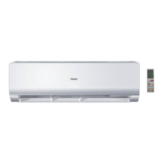
AS09TH3HRA
WARNING
This service information is designed for experienced repair technicians only and is not designed for use by the general public.
It does not contain warnings or cautions to advise non-technical individuals of potential dangers in attempting to service a product.
Products powered by electricity should be serviced or repaired only by experienced professional technicians. Any attempt to service or
Repair the product or products dealt with in this service information by anyone else could result in serious injury or death
2015 (Qingdao Haier Air Conditioner General corp. , Ltd)
All rights reserved. Unauthorized copying and distribution is a violation of law
Haier Group
Version V1
Date 2017-11-28
Advertisement
Table of Contents

Related Manuals for Haier AS09TH3HRA


Summary of Contents for Haier AS09TH3HRA
- Page 1 Repair the product or products dealt with in this service information by anyone else could result in serious injury or death 2015 (Qingdao Haier Air Conditioner General corp. , Ltd) All rights reserved. Unauthorized copying and distribution is a violation of law...
-
Page 2: Table Of Contents
Table of contents Contents 1. Introduction .................... 1 2. Features ....................7 3. Specifications ..................8 4. Sensors list.................... 9 5. Piping diagrams ..................10 6. Printed circuit board connector wiring diagram........11 7. Functions and control ................8. Dimensional drawings ................9. -
Page 3: Introduction
Intuoduction 1 Introduction 1.1 Model name explanation Apply toT1; 220~240V50HZ/1ph DC inverter Indoor units Version number 20TPlatform Platform of indoor units: T (T platform) Nominal cooling capacity (9000BTU/h) Type of indoor unit: S (wall-mounted) Indoor unit Domestic air conditioner... - Page 4 Introduction 1.2 Safety Cautions Be sure to read the following safety cautions before conducting repair work. The caution items are classified into “Warning” and “Caution”. The “Warning” items are especially important since they can lead to death or serious injury if they are not followed closely. The “Caution” items can also lead to serious accidents under some conditions if they are not followed.
- Page 5 Introduction Warning Do not repair the electrical components with wet hands . Working on the equipment with wet hands can cause an electrical shock Do not clean the air conditioner by splashing water. Washing the unit with water can cause an electrical shock.
- Page 6 Introduction Warning Be sure to use an exclusive power circuit for the equipment, and follow the technical standards related to the electrical equipment, the internal wiring regulations and the instruction manual for installation when conducting electrical work. Insufficient power circuit capacity and improper electrical work can cause an electrical shock or fire. Be sure to use the specified cable to connect between the indoor and outdoor units.
- Page 7 Introduction Caution Installation of a leakage breaker is necessary in some cases depending on the conditions of the installation site, to prevent electrical shocks. Do not install the equipment in a place where there is a possibility of combustible gas leaks. If a combustible gas leaks and remains around the unit, it can cause a fire.
- Page 8 Introduction Caution Check to see if the parts and wires are mounted and connected properly, and if the connections at the soldered or crimped terminals are secure. Improper installation and connections can cause excessive heat generation, fire or an electrical shock. If the installation platform or frame has corroded, replace it.
-
Page 9: Features
Features 2.Features Super quiet: Lower noise operation condition A-PAM DC inverter:With adoption of S-TYPE,S-PAM and PHASE control technology to works more stably at low-frequency,and is more energy-saving,mor powerful at high frequency. Long distance air supplying: Heating: When -15 can still heating natural heating maintenance:Heating Holding 10 temperature Confortable sleep The setting temperature and the indoor noise can be adjusted to a more comfortable... -
Page 10: Specifications
Specifications 3.Specifications NOMINAL DISTRIBUTION SYSTEM VOLTAGE NOMINAL CAPACITY and NOMINAL INPUT n i l 2.5(1.0-3.0) 2.8(1.2-3.5) Capacity rated Btu/h 9550(4100-11940) 8500(3400-10240) 0.778 0.775 EER/COP 387.5 ³ 1.2*10 ³ TECHNICAL SPECIFICATIONS 708/190/263 Packaged Dimensions 771/255/330 White Sound Sound level 36/34/30 36/34/30 dB(A) peessure(Hi/Mid/Lo) Domestic air conditioner... -
Page 11: Sensors List
Specifications TECHNICAL SPECIFICATIONS-PARTS cooling heating Air flow rate(high) m³/h 1100/1000/9 0 Speed(Hi/Mid/Lo) 1150/1050/950 Type ML fin- 7HI-HX tube Heat exchanger c t i Removable/Washable/Mildew Proof Air filter Microcomputer Control Temperature control l l o Note: the data are based on the conditions shown in the table below Conversation formulae n i l Kcal/h= KW×860... -
Page 12: Piping Diagrams
Piping diagrams 5 Piping diagrams Domestic air conditioner... -
Page 13: Printed Circuit Board Connector Wiring Diagram
Connector for fresh air Note: Other designations PCB(1) (Indoor Control PCB) 1) CN48 Connector for Forced operation ON / OFF switch 2) FUSE1 Fuse 3.15A/250VAC N_RC UNIT MODEL PCB MODEL 0011800722 AS09TH3HRA-TE4 387* 317* S2/DISPLAY SERIES 324* 325*/498* 387* 317* UNTI MODEL... - Page 14 Printed circuit board connector wiring diagram Domestic air conditioner...
- Page 15 Printed circuit board connector wiring diagram Wiring diagrams 0010593394 Transformer C0N3 C0N1 C0N2 Fresh air CN21 Fan motor CN21' CN18 up-down stepmotor CN11 CN23 left stepmotor CN31 Right stepmotor CN12 CN35 WIFI CN17 Central controller CN48 EMERGENCY SWITCH CN36 AMBIENT TEMP SENSOR PIPING TEMP SENSOR DISPLAY POWER SUPPLY...
-
Page 16: Functions And Control
Functions and control 7.Funcitions and control 7.1 Main functions and control specification 7.1.1 Automatic operation When the running mode is turned to automation after starting the system, the system will first determine the running mode according to the current room temperature and then will run according to the determined mode. - Page 17 Functions and control 7.1.3 Dehumidifying mode. * temperature control range: 16---30℃ * temperature difference: ±1℃ Control feature: send the dehumidifying signal to the outdoor system. When Tr>Ts+2℃, the compressor will be turned on, the indoor fan will operate at the set speed. When Tr is between the Ts and Ts+2℃, the outdoor system will operate at the high dehumidifying frequency for 10 minutes and then at the low dehumidifying mode for six minutes.
- Page 18 Functions and control If Tr<Ts-1℃, the outdoor system will be turned on again, the indoor fan will be at the cold air proof mode. *Indoor fan control manual control: You can choose high, medium, low and automatic speed control. Automatic: When Tr<Ts, high speed. When Ts≤Tr≤Ts+2℃, medium speed.
- Page 19 Functions and control Entering ‘mute’, you can have normal operation or signal control such as timing to finish the strength operation. When the system is at the automatic option with the strength/ mute function, if the system enters the cooling mode, the cooling strength/ mute function will be offered; if the system enters the heating mode, then the heating strength/ mute function will be offered;...
- Page 20 Functions and control 2 centigrade after 1 hour’s operation and will fall 2 centigrade 1 hour later. 3 hours after the preceding operations, the set temperature will be raised for 1 centigrade and the system will keep this status for 3 hours and then close down.
- Page 21 Functions and control 7.1.12 High load protection control The outdoor system will be stopped if the coil temperature is above 65℃ for 2 minutes. The indoor fan will be controlled by the thermostat. The outdoor system can be restarted when the coil temperature is below 42℃...
- Page 22 Functions and control can be confirmed and reported and the outdoor system will be stopped. 7.1.16 Single indoor system operation * Enter condition: First, set the high speed airflow and 30 centigrade set temperature, then press the dormant keys for 6 times within 7 seconds, the system will feedback with 6 rings. * After the system enters the separate indoor system operation mode, the indoor system will operate according to the set mode and neglect the communication signals of the outdoor system.
- Page 23 Functions and control R25℃=23KΩ+2% Temp.(℃) Resistor(KΩ) Temp.(℃) Resistor(KΩ) Temp.(℃) Resistor(KΩ) 266.905 32.215 250.866 30.671 5.87 235.895 29.21 5.65 221.911 27.828 5.44 208.838 26.521 5.24 196.609 25.283 5.04 185.163 24.111 4.86 174.443 4.68 164.399 21.94 4.51 154.983 20.94 4.35 146.153 19.99 4.19 137.87 19.09...
- Page 24 Functions and control R25℃=10KΩ±2% B25℃/50℃=3700K±2% Temp.((℃)) Max.(KΩ) Normal(KΩ) Min.(KΩ) Tolerance(℃) 165.2170 147.9497 132.3678 -1.94 1.75 155.5754 139.5600 125.0806 -1.93 1.74 146.5609 131.7022 118.2434 -1.91 1.73 138.1285 124.3392 111.8256 -1.89 1.71 130.2371 117.4366 105.7989 -1.87 1.70 122.8484 110.9627 100.1367 -1.85 1.69 115.9272 104.8882 94.8149...
- Page 25 Functions and control 20.9688 19.9409 18.9463 -1.13 1.09 20.0176 19.0621 18.1358 -1.11 1.07 19.1149 18.2270 17.3646 -1.08 1.05 18.2580 17.4331 16.6305 -1.06 1.03 17.4442 16.6782 15.9315 -1.03 1.01 16.6711 15.9601 15.2657 -1.01 0.99 15.9366 15.2770 14.6315 -0.98 0.96 15.2385 14.6268 14.0271 -0.96 0.94...
- Page 26 Functions and control 3.7878 3.5654 3.3531 -1.78 1.70 3.6601 3.4416 3.2332 -1.82 1.74 3.5374 3.3227 3.1183 -1.87 1.78 3.4195 3.2085 3.0079 -1.91 1.82 3.3060 3.0989 2.9021 -1.95 1.85 3.1969 2.9935 2.8005 -2.00 1.89 3.0919 2.8922 2.7029 -2.04 1.93 2.9909 2.7948 2.6092 -2.08 1.97...
- Page 27 Functions and control 1.0030 0.9061 0.8179 -3.85 3.51 0.9756 0.8806 0.7941 -3.90 3.55 0.9490 0.8558 0.7711 -3.96 3.60 0.9232 0.8319 0.7489 -4.01 3.64 0.8983 0.8088 0.7275 -4.07 3.69 0.8741 0.7863 0.7067 -4.12 3.74 0.8507 0.7646 0.6867 -4.18 3.78 0.8281 0.7436 0.6672 -4.23 3.83...
-
Page 28: Dimensional Drawings
Seivice diagnosis 8.Dimensional drawings unit:mm 708 9.Center of gravity unit:mm Domestic air conditioner... -
Page 29: Service Diagnosis
Service diagnosis 10. Service Diagnosis 10.1 Caution for Diagnosis The operation lamp flashes when any of the following errors is detected. 1. When a protection device of the indoor or outdoor unit is activated or when the thermistor malfunctions, disabling equipment operation. 2. - Page 30 Service diagnosis 10.3 Error Codes and Description indoor display Code indication Indoor displaying Reference Outdoor fault description panel code indication Page (LED1 flash Only For 498 and times) 498A display other display (Red/Green Time Run) Flash Communication fault between indoor and Indoor and ★...
- Page 31 Service diagnosis 10.3.1 Thermistor or Related Abnormality Indoor Display ★ ■■ / E1 : Room temperature sensor failure ★ / E2: Heat-exchange sensor failure Outdoor display LED1 flash 10 times:Defrost temperature sensor failure LED1 flash 11 times:Suction temperature sensor failure LED1 flash 12 times:Ambient temperature sensor failure LED1 flash 13 times:Discharge temperature sensor failure Method of...
- Page 32 Service diagnosis 10.3.2 EEPROM abnormal Indoor Display E4: Indoor EEPROM error Indoor display ■ ■ F12: Outdoor EEPROM error; Outdoor LED1 flash 1 times ★ Method of The Data detected by the EEPROM are used to determine MCU Malfunction Detection Malfunction When the data of EEPROM is error or the EEPROM is damaged Decision...
- Page 33 Service diagnosis 10.3.3 Indoor fan motor malfunction Indoor Display ■ Method of The rotation speed detected by the Hall IC during fan motor operation is used to determine Malfunction abnormal fan motor operation Detection Malfunction when the detected rotation feedback signal don’t received in 2 minutes Decision Conditions Supposed...
- Page 34 Service diagnosis Check whether Terminal on the outdoor mainboard is well inserted. Reinsert the terminals Is it normal? Electrify the machine again and turn it on in the Cool state with the remote controller. check whether motor can run? Measure the voltage between 1 and 3 of the terminal of fan motor on the mainboard about DC310V, Measure the voltage between 3 and 4 of the terminal about DC15V.
- Page 35 Service diagnosis 10.3.4 Outdoor DC fan motor fault Outdoor display LED1 flash 9 times Method of DC fan motor is detected by checking the fan running condition and so on Malfunction Detection Malfunction when the data of EEPROM is error or the EEPROM is damaged Decision Conditions Supposed...
- Page 36 Service diagnosis 10.3.5 IPM protection Outdoor display: LED1 flash 2 times Method of IPM protection is detected by checking the compressor running condition and so on Malfunction Detection Malfunction ■ The system leads to IPM protection due to over current Decision ■...
- Page 37 Service diagnosis 10.3.6 Over-current of the compressor Outdoor Display: LED1 flash 3 or 24 or 25 times Method of The current of the compressor is too high Malfunction Detection Malfunction when the IPM Module is damaged Decision or the compressor is damaged. Conditions power supply voltage is too low or too high Supposed...
- Page 38 Service diagnosis Electrify the machine again and turn it on with the remote controller, If malfunctions IPM Module is damaged and are reported before or upon the compressor needs replacing. being started up, The compressor is started normally, but malfunctions are reported after it has Repair the power supply run for some time.
- Page 39 Service diagnosis 10.3.7 The communication fault between IPM and outdoor PCB Outdoor display: LED1 flash 4 times Method of Communication is detected by checking the IPM module and the outdoor PCB Malfunction Detection Malfunction ■ The outdoor PCB broken leads to communication fault Decision ■...
- Page 40 Service diagnosis 10.3.8 Power Supply Over or under voltage fault Outdoor display: LED1 flash 6 times The power supply is over voltage Method of An abnormal voltage rise or fall is detected by checking the specified voltage detection circuit. Malfunction Detection Malfunction An voltage signal is fed from the voltage detection circuit to the microcomputer...
- Page 41 Service diagnosis 10.3.9 Overheat Protection For Discharge Temperature Outdoor display: LED1 flash 8 times Method of The Discharge temperature control is checked with the temperature being detected Malfunction by the Discharge pipe thermistor Detection Malfunction when the compressor discharge temperature is above 110℃ Decision Conditions Supposed...
- Page 42 Service diagnosis 10.3.10 The communication fault between indoor and outdoor Indoor display ■■ ★ / E7 outdoor display LED1 flash 15 times Method of Communication is detected by checking the indoor PCB and the outdoor PCB. Malfunction Detection Malfunction ■ The outdoor PCB broken leads to communication fault. Decision ■...
- Page 43 Service diagnosis (A) Check the indoor mainboard. Measure the voltage between Jumpers 3 and 4 of IC1 on the indoor mainboard with a multimeter. Test the outdoor power supply (230VAC and +310VDC) with a multimeter. If the voltage is of a constant value of 0V DCto5V DC If 230VAC is available but 310DC not, the power module is damaged, replace it...
- Page 44 Service diagnosis 10.3.11 Loss of synchronism detection Inverter side current detection is abnormal Outdoor Display LED1 flash 18 times LED1 flash 19 times Method of The position of the compressor rotor can not detected normally Malfunction Detection Malfunction when the wiring of compressor is wrong or the connection is poor; Decision or the compressor is damaged Conditions...
- Page 45 Service diagnosis 10.3.12 High work-intense protection Indoor Display ★★★ / E9 Outdoor display LED1 flash 21 times Method of High work-intense control is activated in the heating mode if the temperature Malfunction being sensed by the heat exchanger thermistor exceeds the limit. Detection Malfunction Activated when the temperature being sensed by the heat exchanger...
-
Page 46: Circuit Diagrams
Circuit diagrams 11. Circuit Diagrams TJC8-04 (立式 4 针) 0.1uF 单片机在线烧写 备注: EE在线烧写 1-3-MODE 1.没有特殊标示下电阻为0603封装, 1-6-RST 精度为±5%; 1-12-SCL 2.没有特殊标示下无极性电容为贴 1-11-SDA TJC8-04 (立式 4 针) 560Ω-0805 片0603封装,耐压50V,精度±20%。 IC4 CAT24C04-SOIC8 5267-04A (原色 - 立式) CN35 显示板 0.01uF 1-48-COM2 KI1/AN9/P11 0.1uF S8B-PH-K-S( 原色 - 卧式 ) 1-41-TXD 1-47-ROOM 100Ω-0805... - Page 47 Circuit diagrams 891WP-1A-C(AC220V-20A- 单刀单掷 ) 备注: 1. 没有特殊标示下电阻为 0603 封装,精度为 ±5 %。 N500 2. 没有特殊标示下无极性电容为贴片 0603 封装,耐压 50V ,精度 ±20% 。 2SD1781KT146R 3. 没有特殊标示下电解电容为 85 ℃。 CN18 RLS4148 室内上电 R500 +12V CN18' 2-33-POWER_ON 4.7K D250 R501 JZC-32F(AC220V-5A- 单刀单掷 ) ULN2003A-SOIC16 IC10 CN11' CON1...
- Page 48 Sincere Forever Haier Group Edited by : Jing Yanqin Haier Industrial Park, No.1, Haier Road Yang Xiaodong 266101, Qingdao, China_ Signed by : He shiquan Http //www.haier.com Approved by: Wu Hongjin Domestic air conditioner...
- Page 49 Repair the product or products dealt with in this service information by anyone else could result in serious injury or death 2016 (Qingdao Haier Air Conditioner General corp. , Ltd) All rights reserved. Unauthorized copying and distribution is a violation of law...
- Page 50 DRemove of front panel Indoor unit Step Procedure Points 1.Features 2.Remove the front panel Hold the front panel by the tabs on the both sides and lift it...
- Page 51 Step Procedure Points 1. Loosen the screw and lift up the casing Loosen the screw cover 2.Lift up the cssing cover Lift up the casing cover Pull the Harness out of the control box and then release the pivots on both sides of the unit to remove the front panel...
- Page 52 Remove the air filters and horizontal flap Step Procedure Points Remove the air filters Lift filter upwards slightly and then pull out downwards Remove the horizontal flap ■ horizontal Release the side of flap is Single pivot and then Release Center of the pivot.
- Page 53 Step Procedure Points Release the screw covers(3EA) Loosen the marked Screw (4EA)
- Page 54 Step Procedure Points Holes (3EA) ■When assembling install the front Release the marked grille horizontally hooks (3EA) and then so as not to stuff Pull the front grille out the flap inside. ■When assembling, Horizontally and remove it make sure these three hooks caught properly.
- Page 55 Release stepping motor and control box Step Procedure Points Loosen screws (2EA) Pull the Harness out of the PCB unit and then Loosen the control Box screws (2EA) . Pull the control box from of the frame and remove it. Harness: Stepping motor and fan motor harness...
- Page 56 Release stepping motor and control box Step Procedure Points Loosen the stepping motor screws (2EA), and then Release the stepping motor...
- Page 57 Removal of Heat Exchanger Step Procedure Points Loosen the marked screw (1EA) Loosen the Screw (1EA) Pull mounting plate and heat exchanger bracket out from Hook of the base frame and then release them.
- Page 58 Step Procedure Points Release fixture plate from the base frame hook and remove it.
- Page 59 Step Procedure Points Loosen the marked screws (4EA). And then Remove the heat exchanger Remove Fan Motor Loosen the marked screws(4EA) and release the cover of fan motor...
- Page 60 Step Procedure Points Loosen the marked screw (2EA) of fan motor up bracket and remove it Screw of fan rotor Screw of Fan Motor up bracket Loosen the marked screw (1EA) of fan motor and remove fan motor and remove it Fan motor bracket(UP) Fan motor assy...
- Page 61 Step Procedure Points Lift up the right part of the fan and remove it Remove horizontal louver and fan motor bracket Release the marked hooks (4EA) and then Pull the guide air plate and remove it Two blades assemble The guide air pltate then remove it...
- Page 62 Remove fan motor bracket and fan bearing Step Procedure Points Pull the hook of fan motor bracket and upward remove it Pull the hook of bearing bracket and upward remove it...
- Page 63 Remove frame work board Step Procedure Points Loosen the marked screw of frame work board Screw of frame work board Pull the hook of frame work board, remove it...
- Page 64 Remove drain pipe and drain pipe stem Step Procedure Points Loosen the marked screw of drain pipe and then remove it Pull the drain pipe stem from base frame and the remove it...
Need help?
Do you have a question about the AS09TH3HRA and is the answer not in the manual?
Questions and answers