
Related Manuals for GMC PBR-0412


Summary of Contents for GMC PBR-0412
- Page 3 Table of Contents I. Main Specifications and Safety Instruction … page3 II.Safety Instruction & Preparation ……………... Page3-5 III. Operation Instruction for E-Models ………… page5-12 … page9-12 HOW TO USE CONE ATTACHMENT TO MAKE A CONE IV. Operation Instruction for Manual Models … page13 V.
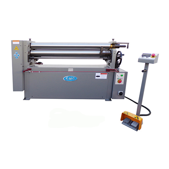
- Page 4 I. MAIN SPECIFICATIONS PBR-0610E MODEL PBR-0412E PBR-04316E PBR-0425E PBR-0510E Max rolling width 51” 51” 51” 61” 81” Max rolling thickness 12GA 3/16” ¼” 10GA 10GA Rolling diameter 3-1/2” 4-3/4” 5-7/8” 4-3/4” 5” Rotate speed 22rpm 16.5rpm 15rpm 16.5rpm 16.5rpm Bending roll up/down motor motor motor...
- Page 5 parts. Gloves and rubber soled footwear is recommended for best footing. 3) Do not overreach. Failure to maintain proper working position can cause you to fall into the machine or cause your clothing to get caught — pulling you into the machine. 4) Keep guards in place and in proper working order.
- Page 6 ·Foundation: The machine requires a plain & stable ground to have an excellent bending performance. It is better to be fixed on 150mm reinforced concrete ground. ·Leveling: Four sheet shims are placed under the adjusting bolt of the foot plate, the machine is leveled by level gauge.
- Page 7 consideration in circle forming. Decide approximate length of material need. Use the formulary “C= πx ID ”(C is Circumference; πis 3.1416; ID is Internal Diameter). Sample:ID=12”, operator need to prepare material length approximate 37.7” or approximate length of material which need. 3.Push the up/down buttons to move the bending roll up/down for right position, and press foot pedal to roll the sheet metal material.
- Page 8 4. Press the foot pedal to make the rolls turn forward and reverse to roll the material back and forth completely to make the part. 5. Press the foot pedal When finished with that part, then turn the cone attachment down 90 degrees. Loose this cone attachment...
- Page 9 Press the foot pedal Loosen this locking bolt, get ready to swing out the top roller. 6.Rotate this handle counter clockwise 90 degrees, and hold and pull the top roller shaft to swing out the top roller, then remove the part out of the top roller.
- Page 10 HOW TO USE CONE ATTACHMENT TO MAKE A CONE: 1. Make the material like circular sector 2. Loosen the set screw on the right coupler and remove it away from the left coupler to disconnect the two couplers. 3. Push the up button switch to move right side of the bending roll up to make it tilt as shown in the picture below.
- Page 11 4.After the bending roll titling degree is set up correctly, please put the coupler back and connect properly, then tighten the set screw to lock the coupler. Make this cone attachment vertical 5. Put the sector material into the rolls, and crank the big hand-wheel to move the pinch roll up till barely touching the sector material, one side of the sector material will keep touching against the cone attachment while rolling it.
- Page 12 6. Push the up button switch or down button switch to adjust the bending roll position. Press the foot pedal to make the rolls turn. 7. Press the foot pedal to make the rolls turn forward and reverse to roll the sector material back and forth completely to make the cone.
- Page 13 8. Loosen and turn the cone attachment down, and swing out the top roller to remove the cone part out. Cone attachment...
- Page 14 IV. OPERATION INSTRUCTION For Models# PBR-0412 / PBR-04316 / PBR-0510 1. Turn main switch on, then press push button “ON” 2. Length of material – necessary to form the designed size circles is the 1 consideration in circle forming. Decide approximate length of material needed, Use the formulary “C= πx ID ”(C is Circumference;...
- Page 15 V. LUBRICATION In this machine we have three grease fittings, please use grease gun to lubricate all of them, 3 times a day, using grease oil Mobil # Dorcia-150 VI. TROUBLESHOOTING Any questions, please call our service # 1-909-947-7787 www.gmcmachinetools.com www.GMCMachineTools.com PROBLEM SOLUTION...
- Page 16 VII. ELECTRICAL SYSTEM 1. Preparation: The main wall breaker needs 30A or 50A, and 10Ga. 3 phase cables 2. Operation of the machine Turn on main power switch, and the indicator light is on, which means the machine Is connected with power supply correctly. Press the right foot pedal, the rolls turn forward-clockwise continuously, release the foot pedal then rolls stop until loosen the pedal.
- Page 20 PARTS LIST FOR PBR-0412E/04316E/0425E/0510E/0610E/0810E/1010E: Part # Description Part # Description Protecting Cover Key 8x45 Hex Bolt M6X10 Worm Shaft Bolt M12X30 Right frame Washer Bottom roller Big gear Sleeve Small gear Adjusting block Bushing Oil cup M8X1 Washer Bolt Shaft Nut M20 Block plate Left frame...
- Page 21 Handle wheel Locking bushing Hex Bolt M6X10 M8X30 Hex bolt M12X85 Key 8x25 Bearing Hex bolt M10X16 Sleeve Sliding block pitch roller Limited block Sleeve Sliding sleeve Gear Top roller Connecting plate Adjusting block Washer 30 Sleeve touch stop switch bracket Hex bolt M5X12 stand Connecting plate...
- Page 23 PART LIST FOR PBR-0412/ PBR-04316 / PBR-0510: Part # Description Part # Description Cover Key 8x45 Allen cup head screws M6X10 Worm shaft Hexagon head bolt M12x30 Right stand Washer Bottom roller Rack wheel Space bush pinion Adjust block spacer bush...
- Page 24 Hand wheel Locking sleeve Dam board Hexagon head bolt M12x85 Key 8x25 Shaft Hexagon head bolt M10x16 Electrical box Slide block Emergency stop Limit roll Foot pedal Slide set Bearing joint Top roller Connecting plate Adjust block Spacer busher Spacer bush Pitch roller Washer Stand...
- Page 25 SAFETY INSTRUCTION WARNING: THIS IS A VERY DANGEROUS MACHINE! FAILURE TO FOLLOW THE SAFETY RULES MAY RESULT IN SERIOUS PERSONAL INJURY As with all machinery there are certain hazards involved with operation and use of the machine. Using the machine with respect and caution will considerably lessen the possibility of personal injury.
- Page 26 disconnected before work is done. 9) Machinery must be anchored to the floor. 10) Use the right tool. Know the tool you are using — its application, limitations, and potential hazards. Don’t force a tool or attachment to do a job it was not designed for. 11) Stay alert, Watch what you are doing;...
- Page 28 Note: This manual is only for your reference. The machines design and specifications are subject to change without prior notice.
Need help?
Do you have a question about the PBR-0412 and is the answer not in the manual?
Questions and answers