Table of Contents
Advertisement
Quick Links
Advertisement
Table of Contents

Related Manuals for HDBaseT SuperSlimHDbaseT70


Summary of Contents for HDBaseT SuperSlimHDbaseT70
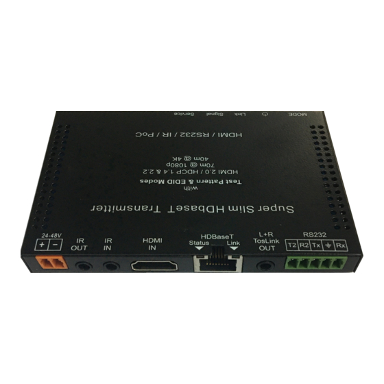
- Page 1 SuperSlimHDbaseT 70 User Manual SSH70-T (Transmitter) SSH70-R (Receiver) 4K HDBaseT Extender 70m @1080p or 40m @4K SSH70 supports: HDMI 2.0, Test Pattern, Down-Scaler, EDID & HDCP control, Audio de-embed, CEC & Temperature control, diagnostics, iPoC...
-
Page 2: Table Of Contents
Contents FEATURES ....................4 CONNECTORS AND CONTROLS............4 Front........................... 4 SSH70-T........................4 SSH70-R........................4 Rear..........................5 SSH70-T ........................5 SSH70-R........................5 USING THE SSH70-T AND SSH70-R ........... 6 RJ-45 WIRING..................7 TEST PATTERN AND KEEP-ALIVE FEATURES......... 7 DOWN-SCALING..................7 CONNECTING TO THE IR PORTS ............7 RS232 CONTROL COMMANDS ............ - Page 3 After Sales Service....................16 Thank you for purchasing the SSH70 Extender Set. This HDBaseT extender is designed with the professional AV installers in mind. The many extensive features assist in system integration, validation and maintenance. It is still the slimmest HDBaseT extender in the world with tremendous flexibility and extraordinary capabilities.
-
Page 4: Features
The SSH70 HDBaseT Extender set supports all input resolutions to 4K60 4:4:4, with bi- directional IR, and two independent pass-through RS232 ports. The main RS232 channel (Tx/Rx) is also used for controlling the many features. The second RS232 channel (T2, R2) can also be used for RTS/CTS handshaking. -
Page 5: Rear
In this way it is much safer to connect to other HDBaseT devices such as projectors with built-in HDBaseT. Extracted Audio output is available as Analogue L/R (3.5mm stereo), as well as optical Mini-Toslink (S/PDIF). -
Page 6: Using The Ssh70-T And Ssh70-R
Using the SSH70-T and SSH70-R Connect a video source to the Transmitter (SSH70-T) HDMI input connector and the remote display device to the Receiver (SSH70-R) HDMI output connector. Ensure the catx cable is wired correctly – see RJ-45 Wiring for connection details. -
Page 7: Rj-45 Wiring
RJ-45 Wiring Both connectors must be wired identically. HDBaseT signals will NOT pass through any Ethernet device, the HDBaseT port on the SSH70-T must be connected directly to the HDBaseT port on the SSH70-R. Please do make sure that the Cat6 cable uses 4 pairs of 23AWG solid copper wires. Do not use inferior copper clad cables as these exhibit much higher resistances. -
Page 8: Rs232 Control Commands
RS232 Control Commands The many features of SSH70 transmitter/receiver units can be managed using RS232 commands (Tx, Rx port). The ASCII commands given in this section use the following port settings: Baud Rate: 57600 Data Bits: Parity: None Stop Bits: Notes: 1. -
Page 9: Output Hdcp Command
Output HDCP Command The following commands are used to select the HDMI Output HDCP modes: Commands Details w is one of following: FORCE-1.4 SET TX HDCP-OPTION w FORCE-2.2 (default: Follow input) FORCE-OFF (cascade mode) FOLLOW-INPUT (default) GET TX HDCP-OPTION Get the output current HDCP mode EDID Commands Any of the following pre-defined EDID settings can be selected as the active EDID when the front EDID switch on the SSH70-T is set to the PRE position. -
Page 10: Video Keep Alive (No Signal Handling) (Timed)
Note: The frame rate is not altered – only the resolution or colour space is changed. The following command selects the 4K handling mode: Commands Details w is one of following options: SET TX 4K-HANDLE w 1080P 4K60-420 (default: Auto) AUTO (default) GET TX 4K-HANDLE... -
Page 11: Safety Temperature
Safety Temperature The following commands can set the Power Off, Warning, and Re-Power temperatures: Commands Details SET TX SAFE-TEMP-ONOFF ON Enable Transmitter safety temperature handling SET RX SAFE-TEMP-ONOFF ON Enable Receiver safety temperature handling SET TX SAFE-TEMP-ONOFF OFF Disable Transmitter safety temperature handling SET RX SAFE-TEMP-ONOFF OFF... -
Page 12: Cec Commands
Signal Error GET TX SIGNAL-ERROR GET TX SIGNAL-ERROR w, w=1, 2, 3… GET RX SIGNAL-ERROR GET RX SIGNAL-ERROR w, w=1, 2, 3… Pulse HPD SET TX PULL-HPD Forces HDMI HPD low for 200ms on SSH70-T SET RX PULL-HPD Forces HDMI HPD low for 200ms on SSH70-R Voltage Values GET TX SUPPOC-VOLTAGE... -
Page 13: Automatic Cec Display Control
HDBaseT port. (default setting) When the Tx is powered from 48V, iPoC mode will be used. The iPoC mode only outputs a voltage to the HDBaseT port only if SET TX HDBTPOC iPOC an iPoC (SSH70) Receiver is detected. It will NOT provide power to any non-iPoC receivers. -
Page 14: Specifications
Specifications General HDMI Version Input: HDMI 2.0 - HDR and HBR supported Max Bandwidth Input: 18 Gbps (4K60 4:4:4) output: 10.2 Gbps (4K60 4:2:40) Input HDCP: 1.4 and 2.2 HDCP Compliance Output HDCP: Fully controlled – Pass, 1.4, 2.2, Cascade mode) RS232 (Control Commands –... -
Page 15: Power Supply
With interchangeable fittings for UK, EU and US Notes: Heat Management: The SSH70 HDBaseT extender has been designed in a revolutionary manner, by directly using the casing as a heatsink for power dissipation. This technique ensures the actual chipsets are running at lower temperatures as the heat generated is dissipated to the environment more efficiently. -
Page 16: Safety Instructions
Safety Instructions To ensure reliable operation of this product as well as protecting the safety of any person using or handling these devices while powered, please observe the following instructions. Do not operate these products outside the specified temperature and humidity range given in the above specifications.
Need help?
Do you have a question about the SuperSlimHDbaseT70 and is the answer not in the manual?
Questions and answers