Table of Contents
Advertisement
Quick Links
Installation and Operating Instructions
FBR-G / TGR-G
with separate rotary agitator drive and discharge screw
Translation of the original German operating and installation instructions for technicians and operators
Read and follow the instructions and safety information!
Technical changes, typographical errors and omissions reserved!
M1730116_en | Edition 29/02/2016
Froling GesmbH | A-4710 Grieskirchen, Industriestraße 12 | www.froeling.com
Advertisement
Table of Contents

Related Manuals for Fröling FBR-G


Summary of Contents for Fröling FBR-G
- Page 1 Installation and Operating Instructions FBR-G / TGR-G with separate rotary agitator drive and discharge screw Translation of the original German operating and installation instructions for technicians and operators Read and follow the instructions and safety information! Technical changes, typographical errors and omissions reserved! M1730116_en | Edition 29/02/2016 Froling GesmbH | A-4710 Grieskirchen, Industriestraße 12 | www.froeling.com...
-
Page 2: Table Of Contents
Table of contents Table of contents General Functional description Safety Hazard levels of warnings Permitted uses 2.2.1 Permitted fuels Wood chips Wood pellets Qualification of staff 2.3.1 Qualification of assembly staff 2.3.2 Personal protective equipment for assembly staff 2.3.3 Qualification of operating staff 2.3.4 Protective equipment for operating staff Design information... - Page 3 Table of contents Operating the system General information Initial startup Filling the store with fuel 5.3.1 Loading of fuel for a partially emptied store with rotary agitator 5.3.2 Loading fuel in an empty store space with a rotary agitator 5.3.3 Blowing in fuel for a partially emptied store with rotary agitator 5.3.4 Blowing in fuel for an empty store with rotary agitator...
-
Page 4: General
General 1 General Thank you for choosing a quality product from Froling. The product features a state-of- the-art design and conforms to all currently applicable standards and testing guidelines. Please read and observe the documentation provided and always keep it close to the system for reference. -
Page 5: Functional Description
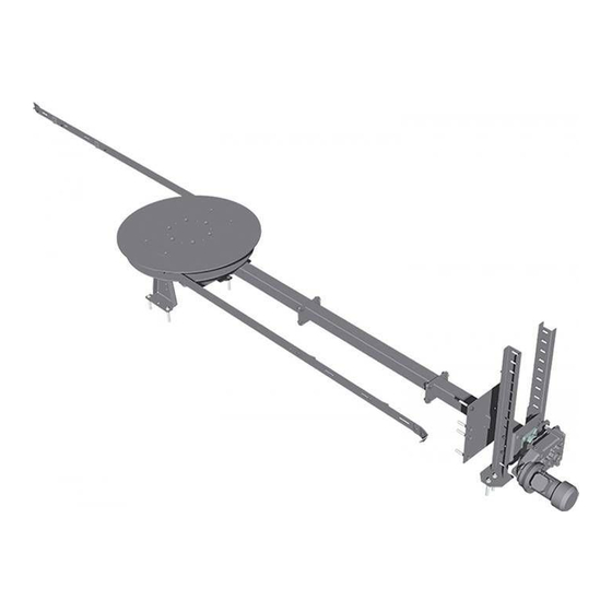
General Functional description 1.1 Functional description TGR torsion arm agitator: FBR spring blade agitator: Rotary agitator geared motor Rotary agitator mitre gear Rotary agitator duct with drive shaft Discharge screw geared motor Rotary agitator plate Gravity shaft Articulated arms with torsion springs Discharge screw closed trough (TGR) Spring piles (FBR) -
Page 6: Safety
Safety Hazard levels of warnings 2 Safety 2.1 Hazard levels of warnings This documentation uses warnings with the following hazard levels to indicate direct hazards and important safety instructions: DANGER The dangerous situation is imminent and if measures are not observed it will lead to serious injury or death. -
Page 7: Permitted Uses
Safety Permitted uses 2.2 Permitted uses Froling’s “FBR-G / TGR-G with separate rotary agitator drive and discharge screw“ is solely designed for discharging fuels from dedicated stores. Only use fuels specified in the “Permitted fuels” section. The unit should only be operated when it is in full working order. It should be operated in accordance with the instructions, observing safety precautions, and you should ensure you are aware of the potential hazards. -
Page 8: Wood Pellets
Safety Permitted uses Wood pellets Wood pellets made from natural wood with a diameter of 6 mm Note on standards Fuel acc. to EN ISO 17225 - Part 2: Wood pellets class A1 / D06 plus / DIN plus certification scheme and/or: General note: Before refilling the store, check for pellet dust and clean if necessary. -
Page 9: Qualification Of Operating Staff
Safety Qualification of staff 2.3.3 Qualification of operating staff CAUTION If unauthorised persons enter the installation room / boiler room: Risk of personal injury and damage to property ❒ The operator is responsible for keeping unauthorised persons, in particular children, away from the system. Only trained operators are permitted to operate the unit. -
Page 10: Requirements At The Installation Site
Safety Design information 2.4.2 Requirements at the installation site ▪ Protect the store against all weather conditions. ▪ Protective structures must be designed in accordance with the applicable standards and regulations Information about the fuel store NOTICE! The fuel store plate provided must be affixed in a conspicuous place in the access area of the store When FILLING the fuel store, observe the system DOCUMENTATION. -
Page 11: Safety Devices
Safety Safety devices 2.5 Safety devices Safety equipment Safety function Limit switch for top of gravity Protection against access to the danger area of the feed/ shaft: discharge screw when the system is switched on ❒ If the inspection cover is opened, the system is switched off via the limit switch ➥... -
Page 12: Residual Risks
Safety Residual risks 2.6 Residual risks The discharge system has been designed and built to comply with the relevant safety directives. Nevertheless by the nature of its operation and function, there are residual risks which cannot be eliminated completely. DANGER When working on the unit with a live power supply: Serious injury possible due to automatic startup! When working on the system or in the store, it is essential that the five safety... - Page 13 Safety Residual risks NOTICE Filling the store when the discharge system is switched off Equipment damage hazard. Due to the high resistance from the weight of the fuel on the rotary agitator arms, the system cannot be started. The drive would be overloaded ❒...
-
Page 14: Technical Information
Technical information Dimensions 3 Technical information 3.1 Dimensions Item Description Diameter of spring blade ⇨ See "Store sizes" [page 15] (FBR) / articulated arm (TGR) D1 Diameter of rotary agitator 1660 1660 1660 plate D2 Diameter of screw 110 mm 150 mm 190 mm D3 Diameter of drive shaft... -
Page 15: Store Sizes
Technical information Store sizes NOTICE Operating the discharge system at too steep a gradient angle The mitre gear can break due to insufficient lubrication! When installing the discharge system, you should therefore ensure: ❒ FBR with wood chips gradient angle α maximum 15° ❒... -
Page 16: Technical Specifications
Technical information Technical specifications ❒ The nominal diameter of the discharge system must be selected according to the side length (A) of the space that runs parallel to the rotary agitator duct. 3.3 Technical specifications Rotary agitator Description Geared motor Power 0.37 kW 0.55 kW... -
Page 17: Installation
Installation Transport and handling 4 Installation 4.1 Transport and handling The discharge system is part-assembled and comes packed on a pallet. ❒ Follow the transport instructions on the packaging! To prevent damage: ❒ Transport components, particularly drive components, with care A door should be provided in the store or a ceiling opening in the silo for bringing in the unit ❒... -
Page 18: Information About Setup
Installation Installation site Store detail Design information 4 Inspection Maintenance opening with class EI 90-C fire resistance rating (e.g. chimney opening door) immediately over the hole in the wall for easy clearance of any blockages from oversized material around the shear edge of the discharge screw. - Page 19 Installation Installation site YES: all/at least half of the screw under rotary NO: screw beside rotary agitator plate agitator plate NOTICE! All, or at least half, of the discharge screw must be positioned beneath the rotary agitator plate! NOTICE! If using the FBR with raising plate, the raising plate must be cut out accordingly.
- Page 20 Installation Installation site Fitting options for discharge screw The separate rotary agitator drive means that the discharge screw can be set up in different ways. Below are some examples using a separate rotary agitator drive with TGR. These illustrations apply to an FBR accordingly. NOTICE! If using pellets it is preferable to use (a) long discharge screw(s) 1x standard discharge screw right 1x standard discharge screw left...
-
Page 21: Wall Opening
Installation Installation site 4.2.2 Wall opening Before erecting the rotary agitator, the customer must make a hole in the wall for both the trough of the discharge screw and the rotary agitator duct. Discharge screw trough Section - Side view: Section - Top view α... -
Page 22: Installing The Discharge System
Installation Installing the discharge system 4.3 Installing the discharge system 4.3.1 Materials supplied with discharge screw A Trough closed (boiler room side) G2 Screw Ø 150 / 200 B Transfer channel (hole in wall) H1 Top of gravity shaft (screw Ø110) C Trough open, multiple parts (store side) H2 Top of gravity shaft (screw Ø150/200) D1 Trough cover - wood chips (standard) -
Page 23: Materials Supplied With Tgr
Installation Installing the discharge system 4.3.3 Materials supplied with TGR P Armset R Rotary agitator plate Q Spacer rings for rotary agitator plate 4.3.4 Materials supplied with rotary agitator A Rotary agitator duct, three-part G2 Gear supports, shortened for horizontal installation (optional) B Drive shaft G3 Extension for gear supports (optional) -
Page 24: Installing The Discharge Screw
Installation Installing the discharge system 4.3.5 Installing the discharge screw ❒ Assemble the open trough (C) ➥ Check the alignment of the flange plates! ❒ Fit open trough (C) with seal to transfer channel (B) ➥ Check the alignment of the flange plates! ❒... - Page 25 Installation Installing the discharge system ❒ Where required: assemble closed trough (A) (depending on model) ❒ Fit closed trough (A) with seal to transfer channel (boiler room side) ❒ Align troughs in store according to installation plan and fix adjustable feet to floor of store ⇨...
- Page 26 Installation Installing the discharge system Discharge screw 110 ❒ Fit safety switch, elbow and thermal discharge valve to top of gravity shaft (H1) ❒ Slide top of gravity shaft over screw and fit to closed trough with seal Discharge screw 110 ❒...
- Page 27 Installation Installing the discharge system Discharge screw 150/200 ❒ Fit flange plate with seal to top of gravity shaft ❒ Fit flange bearing to flange plate on top of gravity shaft ❒ Fit counter bearing for torque support to top of gravity shaft ❒...
-
Page 28: Fitting The Rotary Agitator
Installation Installing the discharge system 4.3.6 Fitting the rotary agitator ❒ Assemble three-part rotary agitator duct (A) ➥ Check alignment of flange plates! ❒ Slide drive shaft (B) into rotary agitator duct ❒ Push rotary agitator duct through hole in wall ➥... - Page 29 Installation Installing the discharge system ❒ Fit adjustable feet (F) to flange plate on boiler room side ➥ Adjust height as required ❒ Fit gear supports (G1) to mitre gear ➥ Adjust height as required ➥ Use shortened gear supports (G2) for horizontal installation (optional) ➥...
- Page 30 Installation Installing the discharge system ❒ Place intermediate plate (J) over mitre gear and fit to flange of rotary agitator duct ➥ Intermediate plate and top edge of trough of discharge screw should be on the same level (3), ⇨ See "Information about setup" [page 18] ➥...
-
Page 31: Aligning The Trough Of The Discharge Screw
Installation Installing the discharge system ❒ Fit rotary agitator plate with spring piles to flange of mitre gear TGR 110-200 ❒ Fit armset (P) with spacer rings (Q) to flange of mitre gear ❒ Fit rotary agitator plate (R) to armset 4.3.7 Aligning the trough of the discharge screw ❒... -
Page 32: Securing The Adjustable Feet And Support Elements
Installation Installing the discharge system 4.3.8 Securing the adjustable feet and support elements ❒ Make 2 holes each in the floor to the left and right of the adjustable feet/support elements ❒ Drill the holes marked ➥ Drill diameter 15 mm ➥... -
Page 33: Closing The Wall Penetration
Installation Installing the discharge system ❒ Pre-tension the torsion spring with the draw tube provided ❒ Insert nut into relevant perforation as indicated in the table ❒ Insert stop screw from above and turn nut ❒ Slowly loosen tension of torsion spring as far as stop, remove draw tube and tighten screw 4.3.10 Closing the wall penetration ❒... -
Page 34: Connecting The System
Installation Connecting the system 4.4 Connecting the system 4.4.1 Electrical connection DANGER When working on electrical components: Risk of electrocution! When work is carried out on electrical components: ❒ Only have work carried out by a qualified electrician ❒ Observe the applicable standards and regulations ➥... -
Page 35: Operating The System
Operating the system General information 5 Operating the system 5.1 General information The steeper the angle (FBR maximum 15° / TGR maximum 10°) at which a rotary agitator is fitted, the more likely that fuel will remain behind when the bunker empties. When operating with pellets it is particularly important to note: ▪... -
Page 36: Filling The Store With Fuel
Operating the system Filling the store with fuel 5.3 Filling the store with fuel Note the following when loading the machine with fuel: ❒ Only use permitted fuels! ⇨ See "Permitted fuels" [page 7] ❒ Remove foreign bodies from the store before filling NOTICE! Systems in which the fuel is delivered by tanker and is blown into the store space must be fitted with a rotary valve. -
Page 37: Loading Of Fuel For A Partially Emptied Store With Rotary Agitator
Operating the system Filling the store with fuel 5.3.1 Loading of fuel for a partially emptied store with rotary agitator If there is still sufficient fuel in the store (the head of the rotary agitator is completely covered with fuel and the rotary agitator arms are not extended), the store can be filled: ❒... -
Page 38: Blowing In Fuel For A Partially Emptied Store With Rotary Agitator
Operating the system Filling the store with fuel ❒ Switch off the power supply to the entire system ➥ Depending on the model via boiler, expansion switch cabinet, etc. ❒ Pile up residual fuel (in the corners and on the walls) in the fuel store on and around the head of the rotary agitator by hand and distribute on discharge screw ➥... -
Page 39: Blowing In Fuel For An Empty Store With Rotary Agitator
Operating the system Filling the store with fuel 5.3.4 Blowing in fuel for an empty store with rotary agitator NOTICE Filling an empty store space with a rotary agitator: With the store space completely empty or almost empty, the rotary agitator arms / spring blades are fully extended. -
Page 40: During Operation
Operating the system During operation If the head of the rotary agitator is not adequately covered by the remaining fuel: ❒ Close all openings to the store to seal out dust ❒ Load a small amount of fuel (approx. 2-3 m³) ➥... -
Page 41: Servicing
Servicing Maintenance schedule 6 Servicing 6.1 Maintenance schedule Discharge screw TGR / FBR W = weekly, M = monthly, Q = quarterly, F = prior to each fill of the store No. Element Interval Operation Motor / gears ❒ Carry out a general visual inspection of drive motors ➥... -
Page 42: Maintenance Contract
Servicing Maintenance contract No. Element Interval Operation Sprinkler system Sprinkler system function test: ❒ Open ball valve only slightly ❒ Heat the sensor to above 95 °C (e.g. with a lighter) ➥ The valve should open and water should flow out. ❒... -
Page 43: Troubleshooting Procedure For Fault Messages
Troubleshooting Procedure for fault messages 7 Troubleshooting The term "fault" is a collective term for warnings, errors and alarms. The boiler reacts differently to the three types of message: WARNING In case of warnings the status LED flashes orange and the boiler initially continues controlled operation. - Page 44 Appendix Addresses 8 Appendix 8.1 Addresses 8.1.1 Address of manufacturer FRÖLING Heizkessel- und Behälterbau GesmbH Industriestraße 12 A-4710 Grieskirchen AUSTRIA TEL 0043 (0)7248 606 0 FAX 0043 (0)7248 606 600 INTERNET www.froeling.com 8.1.2 Address of the installer Stamp Froling GesmbH | A-4710 Grieskirchen, Industriestraße 12 | www.froeling.com...
Need help?
Do you have a question about the FBR-G and is the answer not in the manual?
Questions and answers