Table of Contents
Advertisement
Quick Links
Module Integration Guide
Redpine Signals, Inc. Proprietary and Confidential
M
o
d
u
l
e
I
n
t
e
g
r
a
M
o
d
u
l
e
I
n
t
e
g
r
a
V
V
e
e
r
r
s
s
i
i
o
o
n
n
2
2
RS9113
V
e
r
s
i
o
n
2
V
e
r
s
i
o
n
October 2014
Redpine Signals, Inc.
2107 N. First Street, #680
San Jose, CA 95131.
Tel: (408) 748-3385
Fax: (408) 705-2019
Email:
info@redpinesignals.com
Website:
www.redpinesignals.com
t
i
o
n
G
u
i
d
e
t
i
o
n
G
u
i
d
e
.
.
1
1
.
2
2
.
2
Page 1
Advertisement
Table of Contents

Related Manuals for Redpine Signals RS9113


Summary of Contents for Redpine Signals RS9113
- Page 1 RS9113 Module Integration Guide October 2014 Redpine Signals, Inc. 2107 N. First Street, #680 San Jose, CA 95131. Tel: (408) 748-3385 Fax: (408) 705-2019 Email: info@redpinesignals.com Website: www.redpinesignals.com Redpine Signals, Inc. Proprietary and Confidential Page 1...
- Page 2 Redpine’s sole discretion without any prior notice to anyone. Redpine is not committed to updating this document in the future. Copyright © 2014 Redpine Signals, Inc. All rights reserved Redpine Signals, Inc. Proprietary and Confidential Page 2...
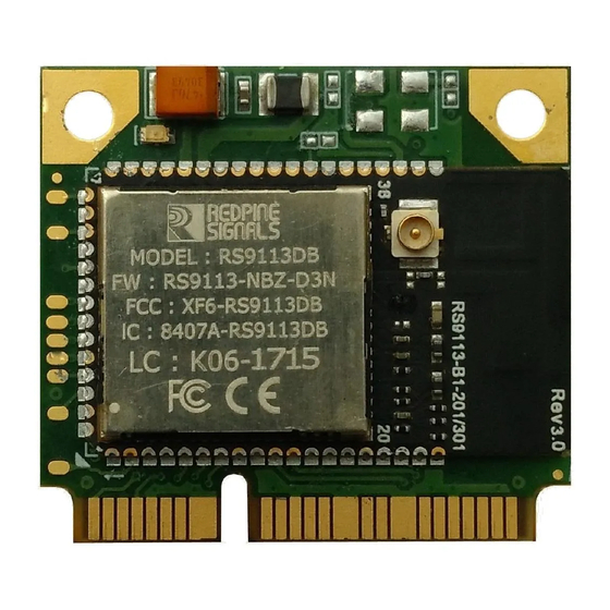
- Page 3 About this Document The RS9113 module is a Wi-Fi, Bluetooth and ZigBee combo module. It is a dual-band 802.11n single-stream module with built-in MAC/BBP, RF and PA, and front-end components. It interfaces to a host processor through SDIO, SPI, UART or USB interfaces. This document provides information that may be used while integrating the module into an end-to-end solution.
-
Page 4: Table Of Contents
Table Of Contents 1 RS9113 module with integrated antenna ...... 7 System Block Diagram ..........7 Reference Schematics and BOM ........8 1.2.1 SDIO mode Interface Schematic (Input supply – 1.8V) ....9 1.2.1.1 Bill of Materials for SDIO mode (Input supply – 1.8V) ..10 1.2.2... - Page 5 Figure 5: USB mode Interface Schematic ........... 19 Figure 6 USB CDC Mode Schematics ........... 22 Figure 7: UART mode Interface Schematic ......... 25 Figure 8: PCB Landing Pattern for RS9113 Module with Integrated Antenna ..................28 Figure 9: Copper Etching Guidelines ........... 29 Figure 10: PCB Top Layer Diagram .............
- Page 6 Table 11: Bill of Material for SPI mode ..........45 Table 12: Bill of Material for USB mode ..........48 Table 13 Bill of Material for USB CDC Mode ........51 Table 14: Bill of Material for UART mode ..........54 Redpine Signals, Inc. Proprietary and Confidential Page 6...
-
Page 7: Rs9113 Module With Integrated Antenna
BOM, Recommended PCB Landing Pattern, Circuit and Layout Guidelines along with a Sample layout of an Evaluation Board using the RS9113 based module with an integrated PCB antenna. The schematics are shown for SDIO, SPI, UART and USB host interface options. -
Page 8: Reference Schematics And Bom
1.2 Reference Schematics and BOM The default values of all the GPIO pins on powering up RS9113 will be set to HIGH and are configured as Output. The following table describes the host interface mode selection for WiSeConnect and Connect-io-n family by using pull resistors on HOST_SEL_1 and HOST_SEL_0 pins. -
Page 9: Sdio Mode Interface Schematic (Input Supply - 1.8V)
100K 8.2nF Rev0.0 OPTION-1 OPTION-2 OPTION-3 RESET Circuitry Title Redpine Signals Confidential RS9113 based Module with integrated antenna -SDIO-1.8V Size Document Number Date: Sheet Figure 2: SDIO mode Interface Schematic – 1.8V Redpine Signals, Inc. Proprietary and Confidential Page 9... -
Page 10: Bill Of Materials For Sdio Mode (Input Supply - 1.8V)
0.1uF CER CHIP C 0.1U 10% X5R 0402 10V 0402 CHIP RES 10K 5% 200PPM 0402 1/10W Panasonic 0402 ERJ-2GEJ103X CHIP RES 100K 5% 200PPM 0402 R10,R12 100K 0402 Panasonic 1/10W ERJ-2GEJ104X Redpine Signals, Inc. Proprietary and Confidential Page 10... -
Page 11: Table 2: Bill Of Material For Sdio Mode (Input Supply - 1.8V)
SWITCH TACTILE SPST-NO 0.02A 15V ALPS SKRAAKE010 SOT23- IC MPU/Reset circuit Maxim Reset MAX6415UK-T MC-146 32.768000kHz Crystal CRYSTAL 32.768KHZ 9PF SMD Epson 12.5 Table 2: Bill of Material for SDIO mode (Input supply – 1.8V) Redpine Signals, Inc. Proprietary and Confidential Page 11... -
Page 12: Sdio Mode Interface Schematic (Input Supply - 3.3V)
100K 8.2nF OPTION-1 OPTION-2 OPTION-3 Rev0.0 RESET Circuitry Redpine Signals Confidential Title RS9113 based Module with integrated antenna -SDIO-3.3V Size Document Number Date: Sheet Figure 3: SDIO mode Interface Schematic – 3.3V Redpine Signals, Inc. Proprietary and Confidential Page 12... -
Page 13: Bill Of Materials For Sdio Mode (Input Supply - 3.3V)
GRM155R71H392KA01D 3.9nF CAP CER 3900PF 50V 10% X7R 0402 Murata GRM155R61A104KA01D C12,C13 0.1uF CER CHIP C 0.1U 10% X5R 0402 10V 0402 CHIP RES 10K 5% 200PPM 0402 1/10W Panasonic 0402 ERJ-2GEJ103X Redpine Signals, Inc. Proprietary and Confidential Page 13... -
Page 14: Table 3: Bill Of Material For Sdio Mode (Input Supply - 3.3V)
SWITCH TACTILE SPST-NO 0.02A 15V ALPS SKRAAKE010 SOT23- IC MPU/Reset circuit Maxim Reset MAX6415UK-T MC-146 32.768000kHz Crystal CRYSTAL 32.768KHZ 9PF SMD Epson 12.5 Table 3: Bill of Material for SDIO mode (Input supply – 3.3V) Redpine Signals, Inc. Proprietary and Confidential Page 14... -
Page 15: Spi Mode Interface Schematic
Note: Ensure a reset assertion time of 20ms. MAX6415 100K 8.2nF OPTION-1 OPTION-2 OPTION-3 RESET Circuitry Rev0.0 Redpine Signals Confidential Title RS9113 based Module with integrated antenna -SPI Size Document Number Date: Sheet Figure 4: SPI mode Interface Schematic Redpine Signals, Inc. Proprietary and Confidential Page 15... - Page 16 Note: Pull resistors on SPI_CS (Chip Select) and SPI_CLK (Serial Clock) can be avoided if the host executes the following sequence. o On power up the RS9113 module is assumed to be in reset mode. Then, initialize the SPI master on the host MCU.
-
Page 17: Bill Of Materials For Spi Mode
0.1uF CER CHIP C 0.1U 10% X5R 0402 10V 0402 CHIP RES 10K 5% 200PPM 0402 1/10W Panasonic 0402 ERJ-2GEJ103X CHIP RES 100K 5% 200PPM 0402 R10,R12 100K 0402 Panasonic 1/10W ERJ-2GEJ104X Redpine Signals, Inc. Proprietary and Confidential Page 17... -
Page 18: Table 4: Bill Of Material For Spi Mode
ERJ-2GEJ105X SWITCH TACTILE SPST-NO 0.02A 15V ALPS SKRAAKE010 SOT23- IC MPU/Reset circuit Maxim Reset MAX6415UK-T MC-146 32.768000kHz Crystal CRYSTAL 32.768KHZ 9PF SMD Epson 12.5 Table 4: Bill of Material for SPI mode Redpine Signals, Inc. Proprietary and Confidential Page 18... -
Page 19: Usb Mode Interface Schematic
8.2nF OPTION-1 OPTION-2 OPTION-3 Rev0.0 RESET Circuitry Title Redpine Signals Confidential RS9113 based Module with integrated antenna -USB Size Document Number Date: Wednesday , October 22, 2014 Sheet Figure 5: USB mode Interface Schematic Redpine Signals, Inc. Proprietary and Confidential... -
Page 20: Bill Of Materials For Usb Mode
CooperBussmann 0603ESDA-MLP IC'S RS9113-B1-301 Module Redpine B1-301 RS9113-B1-031 Buck-Boost Regulator Texas TPS63001 QFN-10 TPS63001DRC Miscellaneous Micro USB Molex 54819-0572 C24,27 Murata GRM1555C1E200JZ01D 20pF CAP CER 20PF 25V 5% NP0 0402 Optional 8.2nF Redpine Signals, Inc. Proprietary and Confidential Page 20... -
Page 21: Table 5: Bill Of Material For Usb Mode
ERJ-2GEJ105X SWITCH TACTILE SPST-NO 0.02A 15V ALPS SKRAAKE010 SOT23- IC MPU/Reset circuit Maxim Reset MAX6415UK-T MC-146 32.768000kHz Crystal CRYSTAL 32.768KHZ 9PF SMD Epson 12.5 Table 5: Bill of Material for USB mode Redpine Signals, Inc. Proprietary and Confidential Page 21... -
Page 22: Usb Cdc Mode Interface Schematic
3.9nF OPTION-1 OPTION-2 OPTION-3 Rev0.0 Rev0.0 RESET Circuitry Title Title Redpine Signals Confidential RS9113 based Module with integrated antenna -USB RS9113 based Module with integrated antenna -USB-CDC Size Size Document Number Document Number Date: Date: Sheet Sheet Figure 6 USB CDC Mode Schematics Redpine Signals, Inc. -
Page 23: Bill Of Materials For Usb Cdc Mode
CooperBussmann 0603ESDA-MLP IC'S RS9113-B1-301 Module Redpine B1-301 RS9113-B1-031 Buck-Boost Regulator Texas TPS63001 QFN-10 TPS63001DRC Miscellaneous Micro USB Molex 54819-0572 Optional C24,27 Murata GRM1555C1E200JZ01D 20pF CAP CER 20PF 25V 5% NP0 0402 8.2nF Redpine Signals, Inc. Proprietary and Confidential Page 23... -
Page 24: Table 6 Bill Of Material For Usb Cdc Mode
SWITCH TACTILE SPST-NO 0.02A 15V ALPS SKRAAKE010 Reset IC MPU/Reset circuit Maxim SOT23-5 MAX6415UK-T MC-146 32.768000kHz Crystal CRYSTAL 32.768KHZ 9PF SMD Epson 12.5 Table 6 Bill Of Material for USB CDC Mode Redpine Signals, Inc. Proprietary and Confidential Page 24... -
Page 25: Uart Mode Interface Schematic
Note: Ensure a reset assertion time of 20ms. MAX6415 100K 8.2nF OPTION-1 OPTION-2 OPTION-3 Rev0.0 RESET Circuitry Redpine Signals Confidential Title RS9113 based Module with integrated antenna -UART Size Document Number Date: Sheet Figure 7: UART mode Interface Schematic Redpine Signals, Inc. Proprietary and Confidential Page 25... -
Page 26: Bill Of Materials For Uart Mode
GRM1555C1E200JZ01D 20pF CAP CER 20PF 25V 5% NP0 0402 Murata GRM155R71H392KA01D 3.9nF CAP CER 3900PF 50V 10% X7R 0402 Murata GRM155R61A104KA01D C12,C13 0.1uF CER CHIP C 0.1U 10% X5R 0402 10V 0402 Redpine Signals, Inc. Proprietary and Confidential Page 26... -
Page 27: Table 7: Bill Of Material For Uart Mode
SOT23-5 MAX6415UK-T MC-146 32.768000kHz Crystal CRYSTAL 32.768KHZ 9PF SMD Epson 12.5 Do Not Populate CHIP RES 0.0R 5% 200PPM 0402 0402 Panasonic ERJ-2GE0R00X 1/10W Table 7: Bill of Material for UART mode Redpine Signals, Inc. Proprietary and Confidential Page 27... -
Page 28: Recommended Pcb Landing Pattern
1.3 Recommended PCB Landing Pattern Figure 8: PCB Landing Pattern for RS9113 Module with Integrated Antenna Redpine Signals, Inc. Proprietary and Confidential Page 28... -
Page 29: Circuit And Layout Guidelines
1.4 Circuit and Layout Guidelines The following are guidelines for integrating the RS9113 module with integrated antenna. 1. The wireless module has 27 ground pads, with two different sizes as mentioned below. Please note that all the ground pads are aligned just across the center of the module on the bottom side. -
Page 30: Sample Layout In Sdio Mode
1.5 Sample Layout in SDIO mode 1.5.1 Top Layer Figure 10: PCB Top Layer Diagram Redpine Signals, Inc. Proprietary and Confidential Page 30... -
Page 31: Bottom Layer
1.5.2 Bottom Layer Figure 11: PCB Bottom Layer Diagram Redpine Signals, Inc. Proprietary and Confidential Page 31... -
Page 32: Component Placement
1.5.3 Component Placement Figure 12 : PCB Component Placement Diagram Redpine Signals, Inc. Proprietary and Confidential Page 32... -
Page 33: U.fl Connector For External Antenna
Figure 13 : u.FL Connector on module [Part no. Hirose U.FL-R-SMT (01)] External Antenna The RS9113 based module with integrated antenna module comes with an integrated on board antenna, and also an u.FL connector, where an external antenna can be connected. A choice between the on board antenna and the external antenna can be made through a software command. - Page 34 This is for general guidance only, as the choice of the antenna will depend on the application. Manufacturer Part No Laird Technologies 0600-00040 Digi International A24-HABUF-P5I Connectblue cB-ACC-27 Connectblue cB-ACC-29 Redpine Signals, Inc. Proprietary and Confidential Page 34...
-
Page 35: Rs9113 Module Without Integrated Antenna
PCB Landing Pattern, Circuit and Layout Guidelines, Antenna Layout Recommendations and Sample layout of an Evaluation Board using the RS9113 based module without integrated antenna. The schematics are shown for SDIO, SPI, UART and USB host interface options. The layout corresponding to this schematic is also shown in this document as a reference. -
Page 36: Reference Schematics And Bom
2.2 Reference Schematics and BOM The default values of all the GPIO pins on powering up RS9113 shall be set to HIGH and are configured as outputs. The following sections provide reference schematics for interconnecting the module over SPI, SDIO, USB host interfaces. -
Page 37: Sdio Mode Interface Schematic (Input Supply - 1.8V)
Note: Ensure a reset assertion time of 20ms. MAX6415 TPS63001 100K 8.2nF OPTION-1 OPTION-2 OPTION-3 BUCK/BOOST SECTION RESET Circuitry Title Redpine Signals Confidential RS9113 based Module without integrated antenna -SDIO-1.8V Size Document Number Date: Sheet Redpine Signals, Inc. Proprietary and Confidential Page 37... -
Page 38: Bill Of Materials For Sdio Mode (Input Supply - 1.8V)
2.2uH FIXED IND 2.2UH 1.6A 73 MOHM LQH3NPN2R2NM0L FB5,FB6,FB7,FB8,FB9,FB10,FB1 FILTER CHIP 120 OHM 1.5A 0402 0402 Murata BLM15EG121SN1D BEAD DIODES Green LED 0603 Lite-On Inc LTST-C190KGKT RS9113-B1-03 Module Redpine B1-03 14X15 RS9113 Redpine Signals, Inc. Proprietary and Confidential Page 38... -
Page 39: Table 9: Bill Of Material For Sdio Mode (Input Supply - 1.8V)
SWITCH TACTILE SPST-NO 0.02A 15V ALPS SKRAAKE010 SOT23- IC MPU/Reset circuit Maxim Reset MAX6415UK-T MC-146 32.768000kHz Crystal CRYSTAL 32.768KHZ 9PF SMD Epson 12.5 Table 9: Bill of Material for SDIO mode (Input supply – 1.8V) Redpine Signals, Inc. Proprietary and Confidential Page 39... -
Page 40: Sdio Mode Interface Schematic (Input Supply - 3.3V)
8.2nF Rev0.0 OPTION-1 OPTION-2 OPTION-3 RESET Circuitry Title Redpine Signals Confidential RS9113 based Module w ithout integrated antenna -SDIO-3.3V Size Document Number Date: Sheet Figure 16: SDIO mode Interface Schematic – 3.3V Redpine Signals, Inc. Proprietary and Confidential Page 40... -
Page 41: Bill Of Materials For Sdio Mode (Input Supply - 3.3V)
14X15 RS9113 ANTENNA TUNING NETWORK Refer to the description in the schematic. Z1,Z2,Z3 0402 Murata GRM1555C1H8R2CZ01D Sample part number for Z1 given here Miscellaneous 2.45GHz &5GHz SMD Antenna Fractus ANT1 Antenna FR05-S1-NO-1-004 Redpine Signals, Inc. Proprietary and Confidential Page 41... -
Page 42: Table 10: Bill Of Material For Sdio Mode (Input Supply - 3.3 V)
SWITCH TACTILE SPST-NO 0.02A 15V ALPS SKRAAKE010 SOT23- IC MPU/Reset circuit Maxim Reset MAX6415UK-T MC-146 32.768000kHz Crystal CRYSTAL 32.768KHZ 9PF SMD Epson 12.5 Table 10: Bill of Material for SDIO mode (Input supply – 3.3 V) Redpine Signals, Inc. Proprietary and Confidential Page 42... -
Page 43: Spi Mode Interface Schematic
Note: Ensure a reset assertion time of 20ms. MAX6415 100K 8.2nF OPTION-1 OPTION-2 OPTION-3 Rev0.0 RESET Circuitry Redpine Signals Confidential Title RS9113 based Module without integrated antenna -SPI Size Document Number Date: Sheet Figure 17: SPI mode Interface Schematic Redpine Signals, Inc. Proprietary and Confidential Page 43... -
Page 44: Bill Of Materials For Spi Mode
0603 Lite-On Inc LTST-C190KGKT IC'S RS9113-B1-03 Module Redpine B1-03 14X15 RS9113 ANTENNA TUNING NETWORK Refer to the description in the schematic. Z1,Z2,Z3 0402 Murata GRM1555C1H8R2CZ01D Sample part number for Z1 given here Redpine Signals, Inc. Proprietary and Confidential Page 44... -
Page 45: Table 11: Bill Of Material For Spi Mode
ERJ-2GEJ105X SWITCH TACTILE SPST-NO 0.02A 15V ALPS SKRAAKE010 SOT23- IC MPU/Reset circuit Maxim Reset MAX6415UK-T MC-146 32.768000kHz Crystal CRYSTAL 32.768KHZ 9PF SMD Epson 12.5 Table 11: Bill of Material for SPI mode Redpine Signals, Inc. Proprietary and Confidential Page 45... -
Page 46: Usb Mode Interface Schematic
Note: Ensure a reset assertion time of 20ms. MAX6415 100K 8.2nF BUCK/BOOST SECTION Rev0.0 OPTION-1 OPTION-2 OPTION-3 RESET Circuitry Title Redpine Signals Confidential RS9113 based Module without integrated antenna -USB Size Document Number Date: Sheet Redpine Signals, Inc. Proprietary and Confidential Page 46... -
Page 47: Bill Of Materials For Usb Mode
0402 Murata BLM15EG121SN1D BEAD DIODES Green LED 0603 Lite-On Inc LTST-C190KGKT CooperBus D2,D3 0603ESDA ESD Suppressor 0603 smann 0603ESDA-MLP IC'S RS9113-B1-03 Module Redpine B1-03 14X15 RS9113 Buck-Boost Regulator Texas TPS63001 QFN-10 TPS63001DRC Redpine Signals, Inc. Proprietary and Confidential Page 47... -
Page 48: Table 12: Bill Of Material For Usb Mode
ERJ-2GEJ105X SWITCH TACTILE SPST-NO 0.02A 15V ALPS SKRAAKE010 SOT23- IC MPU/Reset circuit Maxim Reset MAX6415UK-T MC-146 32.768000kHz Crystal CRYSTAL 32.768KHZ 9PF SMD Epson 12.5 Table 12: Bill of Material for USB mode Redpine Signals, Inc. Proprietary and Confidential Page 48... -
Page 49: Usb Cdc Mode Interface Schematic
OPTION-1 OPTION-2 OPTION-3 Rev0.0 RESET Circuitry Title Redpine Signals Confidential RS9113 based Module without integrated antenna -USB-CDC Size Document Number Date: Wednesday , October 22, 2014 Sheet Figure 19 USB CDC Mode Interface Schematics Redpine Signals, Inc. Proprietary and Confidential... -
Page 50: Bill Of Materials For Usb Cdc Mode
RS9113-B1-03 Module Redpine B1-03 14X15 RS9113 Buck-Boost Regulator Texas TPS63001 QFN-10 TPS63001DRC ANTENNA TUNING NETWORK Refer to the description in the schematic. Z1,Z2,Z3 0402 Murata GRM1555C1H8R2CZ01D Sample part number for Z1 given here Redpine Signals, Inc. Proprietary and Confidential Page 50... -
Page 51: Table 13 Bill Of Material For Usb Cdc Mode
SWITCH TACTILE SPST-NO 0.02A 15V ALPS SKRAAKE010 SOT23- IC MPU/Reset circuit Maxim Reset MAX6415UK-T MC-146 32.768000kHz Crystal CRYSTAL 32.768KHZ 9PF SMD Epson 12.5 Table 13 Bill of Material for USB CDC Mode Redpine Signals, Inc. Proprietary and Confidential Page 51... -
Page 52: Uart Mode Interface Schematic
Note: Ensure a reset assertion time of 20ms. MAX6415 100K 8.2nF Rev0.0 OPTION-1 OPTION-2 OPTION-3 RESET Circuitry Title Redpine Signals Confidential RS9113 based Module without integrated antenna -UART Size Document Number Date: Sheet Figure 20: UART mode Interface Schematic Redpine Signals, Inc. Proprietary and Confidential Page 52... -
Page 53: Bill Of Materials In Uart Mode
Redpine B1-03 14X15 RS9113 RS232 Level Shifter Texas SSOP-16 MAX3232CDBR ANTENNA TUNING NETWORK Refer to the description in the Z1,Z2,Z3 schematic. Sample part number for Z1 0402 Murata GRM1555C1H8R2CZ01D given here Miscellaneous Redpine Signals, Inc. Proprietary and Confidential Page 53... -
Page 54: Table 14: Bill Of Material For Uart Mode
The RF_OUT2 (Module Pin No. 32) signals may be directly connected to an on-board chip antenna, or may be terminated in an SMA connector of any form factor for enabling the use of external antennas. There is NO DC blocking available on RF_OUt1 & RF_Out2. Redpine Signals, Inc. Proprietary and Confidential Page 54... -
Page 55: Recommended Pcb Landing Pattern
2.3 Recommended PCB Landing Pattern Figure 21: PCB Landing Pattern for 9113 Module without Integrated Antenna Redpine Signals, Inc. Proprietary and Confidential Page 55... -
Page 56: Circuit And Layout Guidelines
2.4 Circuit and Layout Guidelines The following are guidelines for integrating the RS9113 module without integrated antenna 1. The Wireless module has one ground pad of size 3.84mm x 3.96mm. An application’s layout must have a provision to include this. -
Page 57: Figure 22: Chip Antenna Layout Recommendations
Ground plane configuration Distance from antenna Topology around antenna Feed point transmission line impedance Trace width Trace length Matching Network PCB substrate thickness PCB substrate dielectric constant. Redpine Signals, Inc. Proprietary and Confidential Page 57... -
Page 58: Sample Layout In Sdio Mode
2.6 Sample layout in SDIO mode This section provides a sample layout of a board that instantiates RS9113 module without integrated antenna. This reference board is an SDIO module with a standard interface into an SDIO slot 2.6.1 Top Layer Figure 23: PCB Top Layer Diagram 2.6.2 Layer2... -
Page 59: Layer3
2.6.3 Layer3 Figure 25: PCB Layer3 Diagram 2.6.4 Bottom Layer Figure 26: PCB Bottom Layer Diagram Redpine Signals, Inc. Proprietary and Confidential Page 59... -
Page 60: Component Placement
2.6.5 Component Placement Figure 27: PCB Component Placement Diagram Redpine Signals, Inc. Proprietary and Confidential Page 60... - Page 61 2) Added note on thermal vias on the thermal pad. 3) Added filtering section for pin USB_VDDA. 4) Minor Edits on the BOM. 5) USB CDC Mode schematics added for module with antenna and Without Antenna. Redpine Signals, Inc. Proprietary and Confidential Page 61...
- Page 62 Revision Version Date Changes 6) Minor Edits on Landing pattern. Redpine Signals, Inc. Proprietary and Confidential Page 62...
Need help?
Do you have a question about the RS9113 and is the answer not in the manual?
Questions and answers