Sign In
Upload
Manuals
Brands
Redpine Signals Manuals
Wireless modules
RS9113
Redpine Signals RS9113 Manuals
Manuals and User Guides for Redpine Signals RS9113. We have
2
Redpine Signals RS9113 manuals available for free PDF download: Integration Manual, Installation Manual
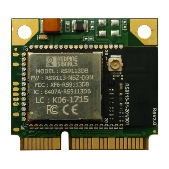
Redpine Signals RS9113 Integration Manual (62 pages)
Brand:
Redpine Signals
| Category:
Wireless modules
| Size: 2 MB
Table of Contents
Table of Contents
4
Figure 1: RS9113 Module with Integrated Antenna
7
Reference Schematics and BOM
8
1 RS9113 Module with Integrated Antenna
7
System Block Diagram
7
Table 1: Host Interface Selection
8
Figure 2: SDIO Mode Interface Schematic - 1.8V
9
Table 2: Bill of Material for SDIO Mode (Input Supply - 1.8V)
11
Figure 3: SDIO Mode Interface Schematic - 3.3V
12
SDIO Mode Interface Schematic (Input Supply - 3.3V)
12
Bill of Materials for SDIO Mode (Input Supply - 3.3V)
13
Table 3: Bill of Material for SDIO Mode (Input Supply - 3.3V)
14
Figure 4: SPI Mode Interface Schematic
15
SPI Mode Interface Schematic
15
Bill of Materials for SPI Mode
17
Table 4: Bill of Material for SPI Mode
18
Figure 5: USB Mode Interface Schematic
19
USB Mode Interface Schematic
19
Bill of Materials for USB Mode
20
Table 5: Bill of Material for USB Mode
21
Figure 6 USB CDC Mode Schematics
22
USB CDC Mode Interface Schematic
22
Bill of Materials for USB CDC Mode
23
Table 6 Bill of Material for USB CDC Mode
24
Figure 7: UART Mode Interface Schematic
25
UART Mode Interface Schematic
25
Bill of Materials for UART Mode
26
Table 7: Bill of Material for UART Mode
27
Antenna
28
Figure 8: PCB Landing Pattern for RS9113 Module with Integrated
28
Recommended PCB Landing Pattern
28
Circuit and Layout Guidelines
29
Figure 9: Copper Etching Guidelines
29
Figure 10: PCB Top Layer Diagram
30
Sample Layout in SDIO Mode
30
Top Layer
30
Bottom Layer
31
Figure 11: PCB Bottom Layer Diagram
31
Component Placement
32
Bill of Materials for SDIO Mode (Input Supply - 1.8V)
10
SDIO Mode Interface Schematic (Input Supply - 1.8V)
9
Figure 12 : PCB Component Placement Diagram
32
Figure 13 : U.fl Connector on Module
33
Figure 14: RS9113 Module Without Integrated Antenna
35
Reference Schematics and BOM
36
U.fl Connector for External Antenna
33
2 RS9113 Module Without Integrated Antenna
35
System Block Diagram
35
Table 8: Host Interface Selection
36
SDIO Mode Interface Schematic (Input Supply - 1.8V)
37
Bill of Materials for SDIO Mode (Input Supply - 1.8V)
38
Figure 15: SDIO Mode Interface Schematic - 1.8V
38
Table 9: Bill of Material for SDIO Mode (Input Supply - 1.8V)
39
Figure 16: SDIO Mode Interface Schematic - 3.3V
40
SDIO Mode Interface Schematic (Input Supply - 3.3V)
40
Table 10: Bill of Material for SDIO Mode (Input Supply - 3.3 V)
42
SPI Mode Interface Schematic
43
Bill of Materials for SPI Mode
44
Table 11: Bill of Material for SPI Mode
45
USB Mode Interface Schematic
46
Bill of Materials for USB Mode
47
Figure 18: USB Mode Interface Schematic
47
Table 12: Bill of Material for USB Mode
48
Figure 19 USB CDC Mode Interface Schematics
49
USB CDC Mode Interface Schematic
49
Table 13 Bill of Material for USB CDC Mode
51
Figure 20: UART Mode Interface Schematic
52
UART Mode Interface Schematic
52
Bill of Materials in UART Mode
53
Table 14: Bill of Material for UART Mode
54
Figure 21: PCB Landing Pattern for 9113 Module Without Integrated Antenna
55
Recommended PCB Landing Pattern
55
Antenna Layout Recommendations
56
Circuit and Layout Guidelines
56
Figure 22: Chip Antenna Layout Recommendations
57
Figure 23: PCB Top Layer Diagram
58
Figure 24: PCB Layer2 Diagram
58
Layer2
58
Sample Layout in SDIO Mode
58
Top Layer
58
Bottom Layer
59
Figure 25: PCB Layer3 Diagram
59
Figure 26: PCB Bottom Layer Diagram
59
Layer3
59
Component Placement
60
Bill of Materials for USB CDC Mode
50
Bill of Materials for SDIO Mode (Input Supply - 3.3V)
41
Figure 27: PCB Component Placement Diagram
60
Advertisement
Redpine Signals RS9113 Installation Manual (42 pages)
n Link Module Driver
Brand:
Redpine Signals
| Category:
Wireless modules
| Size: 1 MB
Table of Contents
Table of Contents
3
Introduction
5
Definitions, Acronyms and Abbreviations
5
Onebox Driver - Setup Requirements
6
Hardware Requirements
6
Software Requirements
6
Extraction of the Driver Package
6
Compilation Procedure on Various Platforms
8
Software Boot Loader Flashing
11
Software Boot Loader Upgradation
13
Onebox-Mobile™ in Wifi Only Mode
14
Loading SDIO Stack Modules (Applicable Only if SDIO Interface Is Selected by User)
14
Installation Procedure in Client Mode
14
Printing Supplicant Scan Results
17
Deep Sleep
17
Connecting to Hidden AP
17
Installation Procedure in Accesspoint Mode
18
Installation Procedure in Wifi-Direct Mode
20
Autonomous GO Mode
21
Onebox-Mobile™ Coexistence Driver in Wifi + BT Classic Mode
22
Note: the Initialization Procedure Mentioned below will be Applicable to both USB and SDIO Interfaces.loading SDIO Stack Modules (Applicable Only if SDIO Interface Is Selected by User)
22
Installation Procedure
22
Installation and Usage of Bluetooth Manager
24
Onebox-Mobile™ Coexistence Driver in Wifi +BLE Mode
27
Note: the Initialization Procedure Mentioned below will be Applicable to both USB and SDIO Interfaces.loading SDIO Stack Modules (Applicable Only if SDIO Interface Is Selected by User)
27
Installation Procedure
27
Advertise Mode
28
Scanning Mode
28
Master Mode Connected State
28
Slave Mode Connected State
28
Onebox-Mobile™ Coexistence Driver in Wifi+Zigbee Mode
30
Driver Installation Procedure
30
Building and Running the Sample HA Switch Application
30
About Sample Application
30
Host API Folder Structure
30
Application State Machine
31
Stack Callbacks
31
Building and Running the HA Sample Switch Application
32
Driver Un-Installation Procedure
33
Driver Information
34
Driver Statistics
34
Disabling Prints in the Driver
34
Starting DHCP Server/Client
35
Appendix
36
Iperf Cross Compilation
36
Configuration of Kernels from 3.13 to 3.16 to Support the Driver
37
BT Porting for Android
39
Advertisement
Related Products
Redpine Signals RS9110-N-11-22
Redpine Signals RS9110-N-11-24
Redpine Signals RS9110-N-11-28
Redpine Signals RS9110-N-11-26
Redpine Signals RS9116
Redpine Signals RS9110-N-11-02
Redpine Signals RS9110-N-11-03
Redpine Signals RS9113DB
Redpine Signals RS9113 EVB
Redpine Signals RS9113SB
Redpine Signals Categories
Motherboard
Wireless modules
Control Unit
Server
Test Equipment
More Redpine Signals Manuals
Login
Sign In
OR
Sign in with Facebook
Sign in with Google
Upload manual
Upload from disk
Upload from URL