
Related Manuals for BZB Gear BG-Commander


Summary of Contents for BZB Gear BG-Commander
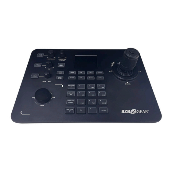
- Page 1 BG-Commander PTZ Camera Controller User Manual CONTACT 1.888.499.9906 | support@bzbgear.com | bzbgear.com FOLLOW US...
-
Page 2: Product Description
Thank You! Thank you for purchasing the BG-Commander IP/Serial PTZ joystick controller. This manual will help you familiarize yourself with the capabilities and functions of this device. Before setting this device up it is recommended that you read this manual in its entirety to ensure optimal performance. This product has been designed for years of trouble-free use. - Page 3 1.2 Product Features • Supports IP and analog control modes • Supports VISCA over IP, ONVIF, Pelco-P/D, and VISCA protocols • Variable speeds for all control axes • Zoom can be controlled by twisting the control handle or the dedicated zoom knob •...
- Page 4 1.4 System connection diagram (1) Network connection video conference camera Dome camera Camera (2) RS485 connection diagram. Control output: The RS485+ of the camera is connected to Ta of the controller, and the RS485- of the camera is connected to the Tb of the controller. -03-...
- Page 5 (3) RS 422 connection diagram *7 cameras max VISCA RS422 VISCA RS422 VISCA RS422 When using RS422 bus connection mode, the third pin (Ra) of the controller is connected to the TXD Controller Camera IN- of the camera, the fourth pin (Rb) of the controller is connected to the TXD IN+ of the camera, the first pin (Ta) of the controller is connected to the RXD IN- of the camera, and the...
- Page 6 (4) Connection between cameras Using RS422 bus cascade connection mode, the output of camera 1 is connected to the input of camera 2, the output of camera 2 is connected to the input of camera 3, and so on. As below: VISCA Equipment CAMERA1 CAMERA2...
-
Page 7: Buttons Description
2.Buttons Description 2.1 Buttons Description [AUTO EXPOSURE]: Click the button to enter the automatic adjustment screen exposure mode. [AUTO WHITE BALANCE]: Click the button to select the white balance setting [AUTO FOCUS]: Click the button to set the focus of the camera on the object [CAM1 - 7]: Switch devices quickly [SETUP/MENU]: 1. - Page 8 Controller Description setting The joystick ID of camera can be filled in 1-7; after Camera adding camera all information press [ENTER] to save. 1.Add network Optional: VISCA (UPD), SONY VISCA (UDP), VISCA (TCP), device Protocol ONVIF, select the corresponding protocol of the camera Camera IP address IP address Port...
- Page 9 [0-9]: Number key preset (Press and hold to set preset), (short press to recall preset) Example: • Set No. 1 preset: Move the camera to the position where you want to set preset- press and hold [1] • Recall No.1 preset: short press [1] [ESC]: Exit [ENTER]: Confirm 2.2 Joystick rotations description...
-
Page 10: Add Device
Keyboard Settings 1. Add Network Device 3. Add device 2. Add Analog Device 3. Device List 4. Network Attribute: Static 3.1 Add network device 5. Language: English 6. Button Tone: Off Use the controller to add LAN devices as follows: 7. - Page 11 3.2 Add analog device Native IP 192.168.0.185 Camera Analog Device Network I/F ONVIF Target IP 192.168.0.181 Camera : 1 Analog interface : 8999 PELCO-D Protocol : Target I/F PELCO-D 192.168.0.245 Address : baud rate 9600 Baudrate : 9600 Address : Analog Active I/F (1) Long press the button on top of the joystick handle to switch the analog mode.
-
Page 12: Network Configuration
5. Network Configuration 5.1 Homepage connection and login Connect the power cable of the controller and connect the network cable. After keyboard start-up is complete, the device IP: 192.168.x.xxx will be displayed on the display. Enter this IP address into the browser to access the configuration page. The initial login is: username: admin password: none (1) Connect the controller and computer in the same LAN, enter the controller IP address in the... - Page 13 (3) Click button to add and modify device parameters in the local area network, the page displays as follows: Input the device number, corresponding IP address, port number and username. Click Save. -12-...
- Page 14 5.2 Web network settings LAN settings can modify the device's IP acquisition method and port parameters, as shown below: Static address (STATIC): User defined IP address Dynamic address (DHCP) (default): The controller will automatically request an IP address from the router, after the request is successful it will be displayed on the display as: “Local IP: xxx.xxx.xxx.xxx”...
- Page 15 5.4 System reset Clear all data and perform a factory reset. 5.5 Restart Perform a reboot of the controller. 5.6 Import configuration Import a previous configuration. -14-...
- Page 16 5.7 Export configuration Export the related information of the current controller added multiple devices, which can be exported to other controller devices. -15-...
-
Page 17: Troubleshooting
5.8 Version information Display the software and hardware information of the current controller. 6. Troubleshooting 1. If the screen displays "Connection failed", check IP information is correct for the camera. Verify controller and camera are on the same subnet. 2. If the screen displays "Username and password are incorrect", please check whether the added device username and password are correct. -
Page 18: Tech Support
7. Tech Support Before contacting tech support, we may have answered your question already! Visit our BZBGEAR support page at bzbgear.com/support for valuable information on our products. Here you will find our Knowledge Base (bzbgear.com/knowledge-base) consisting of tutorials, quick start guides, and step-by-step troubleshooting instructions. Also visit our YouTube channel BZB TV at youtube.com/c/BZBTVchannel for help setting up, connecting, and other how-to videos regarding our products.
Need help?
Do you have a question about the BG-Commander and is the answer not in the manual?
Questions and answers