Table of Contents
Advertisement
Quick Links
Advertisement
Table of Contents

Related Manuals for HATO SWING 400


Summary of Contents for HATO SWING 400
- Page 1 FOR SWING GATES with slowdown (HELB9C) REV 1.7 ASSEMBLY AND OPERATION MANUAL The following assembly and operating manual is an inseparable part of the HATO SWING swing gate drive, it is intended only for qualified installers and should be read thoroughly and...
- Page 2 completely before starting the assembly. The manual applies only to the drive for the gate, not to the entire device which is the `` automatic gate ''. RECOMMENDATIONS AND PRECAUTIONS FOR INSTALLATION ► These operating instructions are intended only for properly licensed installers, who know the rules of good engineering practice and safety devices to protect against hazards, installed in gates, doors and motorized gates (observe the applicable standards and regulations).
- Page 3 ► In the event of any changes made to the product without the consent of the manufacturer, failure to comply with the safety rules and applicable standards referred to in this manual, HATO POLSKA S.C. bears no responsibility for property damage, disability or damage caused to the animals.
-
Page 4: Safety Notes
The SWING 400/600 operator has been designed and manufactured to open gates with a maximum leaf length of 5 m and a maximum weight of 200 kg. and the area of the wing building 2m2. The HATO company is not liable if the SWING 400/600 drive is used for purposes other than those specified. -
Page 5: Initial Check
4 - Check that the electrical installation meets the parameters specified by the drive. DECLARATION OF CONFORMITY The HATO SWING 400/600 drive meets the requirements specified in the following regulations: Complies with the conditions set out in the Machinery Directive 2006/42 / EC Annex II section B together with later changes. -
Page 6: Technical Specification
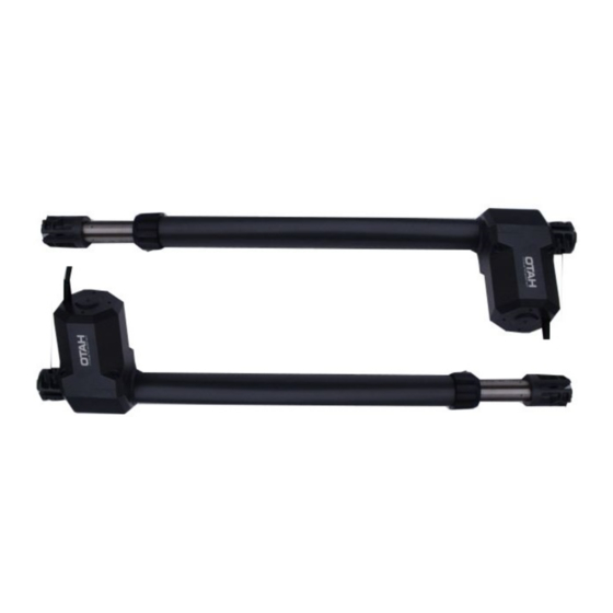
HATO remote control 1 pc Photocells 1 set * the given list of parts applies to the full set of automation products for the HATO SWING swing gate TECHNICAL SPECIFICATION SWING 400 SWING 600 Motor supply voltage 230V AC +/-10% 50Hz... - Page 7 OUTER DIMENSIONS OF THE ACTUATOR...
-
Page 8: Handling Emergency Situations
Mounting bracket mounting bracket on the engine side on the piston side HANDLING EMERGENCY SITUATIONS To manually lock and unlock the wing, put the included wrench on screw C (see FIG. 1). - Page 9 ASSEMBLY In order to properly install the SWING 400/600 drive, follow the steps below: 1 - Open the package and remove the SWING 400-600. Check that the drive has not been damaged during transport. 2 - Check that the gate leaf is perfectly horizontal.
- Page 10 5 - Mount the drive on plate A and fix it with the appropriate screw. 6 - Close the gate and remove the pin D by unscrewing it to the end of its stroke. 7 - Screw in the tube D making 1 full turn through 360 °. 8 - Take plate B, insert it into the hole in the pin and rest it on the sash crossbar.
-
Page 12: Mode Of Action
DEVICE DESCRIPTION PURPOSE The HELB9C controller is designed for gate drives using two 230Vac motors / actuators with a power of up to 500W. Perfect for private properties and companies. The applied system of variable coding of Microchip transmitters makes the system inaccessible to an unauthorized person. - Page 13 Motor supply voltage AC 230V+/-10% 50Hz Vac Standby power consumption <3W (without accessories) Radio receiver 433.92MHz OOK Transmitter type HELB9C HATO company compatible with Keeloq transmission Memory of transmitters 32 pcs Maximum engine power <=500W CH2 channel maximum load 1A/30VDC, 0.3A/60VDC, capacity 0.5A/125VAC...
-
Page 14: Controller Installation
DIMENSIONS CONTROLLER INSTALLATION Before starting the installation, make sure that all safety recommendations are met. Any installation work may only be performed by qualified personnel. Electrical installation and connection of electronic devices may only be performed by persons with appropriate electrical qualifications. - Page 15 Set the power of the motors with the potentiometer to a value close to the minimum. You should be aware that the maximum force of the actuators is 1600N and using the maximum value on a delicate gate may damage it. When starting, gradually adjust the engine power to the weight of the leaf.
- Page 16 The electric strike is connected to an additional potential-free CH2 contact. When selecting the tap, one should take into account the limitations of the relay load capacity (see TECHNICAL DATA). An external power source appropriate to the selected model is required. CH2 (pin 1) –...
- Page 17 the LAMP connector: N – the neutral wire of the lamp L – lamp phase wire Fluorescent lamps must not be used as traffic lights. 4.7. Power connection The last stage of connection is to connect the controller power supply, connect in turn the wires: PE –...
-
Page 18: Connection Diagram
contrary - reduces it. The regulation should be carried out in accordance with the applicable standards. Program the engines operation - according to the procedure described in paragraph Programming. Properly configure the controller and program the remote control transmitters. Check that the wings stop correctly in the end positions. If not, check the correctness of connection and repeat the procedure of programming the leaves operation. - Page 19 If you do not use the STOP and / or PHOTO inputs, put on the STOP-COM and / or FOTO IN-FOTO COM jumpers.
- Page 20 Before starting the gate, the controller checks the correct operation of the photocells by disconnecting and connecting the transmitter power supply. In case it is impossible (e.g. with battery or external power supply), connect the contact of the photocell receiver between the PHOTO COM input and the PHOTO IN input.
-
Page 22: Programming Settings
PROGRAMMING SETTINGS Programming the controller is done using the "SETUP", "LEARN" buttons, LED1 and LED2 diodes located on the controller board and 4 function switches. Programming can only take place when the gate is in stop state. If we start programming the controller, when the auto-closing time is counting down, the countdown will be stopped and to close the gate, press the SBS button or the remote control transmitter. -
Page 23: Autoclose Function
Release the SETUP button. SETUP The LED1 will flash rapidly. Within 5s, start setting the time. Press SETUP x times. One press corresponds to 15s. Each pressing is signaled by the lighting of the diode. If the SETUP button is not pressed within these 5s, the controller will set the time to 0s. - Page 24 Within 5s, start setting the time. Press SETUP x times. One press corresponds to 15s. Each pressing is signaled by the lighting of the diode. If the button is not SETUP pressed within these 5 seconds, the controller will set the default time. After 3s from the last press, the LED1 will flash 3 times.
- Page 25 ATTENTION! The photocell input is ignored during the procedure. Adjust the thrust on the FORCE potentiometer in accordance with the applicable standards. Place the wings in the fully closed position. M1CL M2CL Hold down the SETUP button. SETUP The LED1 will turn on then turn off and turn on again.
- Page 26 The M2 leaf will open at a slow speed. LED1 will light up. After reaching the limit switch, the M2 leaf will stop in the fully open position. LED1 M2OL will turn off. To assign positions manually, press the SBS sequential control button for less than 3s or the transmitter button assigned to this function.
-
Page 27: Soft Start Function
To assign positions manually, press the SBS sequential control button for less than 3s or the transmitter button assigned to this function. LED1 will turn off Press the SBS sequence control button for less than 3s or the transmitter button assigned to this function. - Page 28 Release the SETUP button. SETUP LED1 will start blinking rapidly. Within 5s, start setting the time. Press SETUP x times. One press corresponds to 1s. Each pressing is signaled by the lighting of the diode. If the button is SETUP not pressed within these 5s, the controller will set the time to 0s.
- Page 29 seconds, and the M1 leaf is controlled from the WI input. To activate the ELECTRIC DOOR LOCK function, set the CH2 / EZ switch to the ON position. To turn on the transmitters control function, set the CH2 / EZ switch to the OFF position.
- Page 30 that has not been programmed will replace the button previously programmed in that function. A button previously programmed to one function, after being programmed to another, only works in the other function. Programowanie nadajnika do funkcji sterowania sekwencyjnego SBS. Hold down the LEARN button for less than LEARN The LED will flash rapidly.
- Page 31 LED2 blinking three times. 2 blinks indicate full memory. 1 blink means the end of the learning time. After correct programming, we have another 10s to program the other transmitters, etc. To finish the procedure, wait 10 seconds from the last programming or shortly press the LEARN button.
-
Page 32: Led Indication
Within 5 seconds, press the button of the transmitter you want to program. (Correct programming is signaled by 3 blinks of LED2) Validate the operation. When a programmed button is pressed, the operation should follow the assigned function. SIGNALING OF STATES AND ERRORS DIODE/IE STATE OF NORMAL ACTIVE... -
Page 33: Terms Of Warranty
The repair will be made as soon as possible, not exceeding 14 days from the date of delivery of the device to the HATO POLSKA Service Center. The guarantor reserves the right to extend the above period in justified cases. - Page 34 The buyer is obliged to notify the seller about the defect within 2 days from the date of its disclosure This warranty covers only HATO products installed and used in Poland An unfinished and / or non-stamped warranty card is invalid The warranty does not cover the costs of disassembly, reassembly and commissioning of the product as well as transport to the HATO service.
- Page 36 HATO TRADE SP. Z O.O. ul. Tunelowa 57 40-676 Katowice POLAND tel. 032-785-25-42 www.hato.pl Warehouse and sales ul. Żeromskiego 1 41-205 Sosnowiec DISTRIBUTOR/SELLER...
Need help?
Do you have a question about the SWING 400 and is the answer not in the manual?
Questions and answers