
Related Manuals for KPS KPS-CF100


Summary of Contents for KPS KPS-CF100
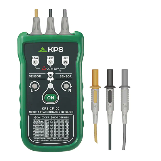
- Page 1 MANUAL DE INSTRUCCIONES INSTRUCTION MANUAL Comprobador de fases/giro Phases/rotation indicator...
-
Page 2: Table Of Contents
ÍNDICE ÍNDICE Introducción ............1 Reemplazo y eliminación de las pilas .....12 Accesorios............1 Especificaciones ........14 Información de seguridad .........2 Lista de tablas Símbolos............4 1. Símbolos ..........4 Componentes del aparato........5 2. Requisitos para la prueba Utilización del comprobador de fiabilidad del motor ........10 de fases y de rotación de motores ....6... -
Page 3: Introducción
Introducción Información de seguridad El comprobador de secuencia de fases y rotación de motores es un instrumento portátil que funciona con PRECAUCIÓN batería diseñado para detectar el campo rotatorio de Identifique las condiciones y acciones que sistemas trifásicos y determinar la dirección de rotación pueden dañar el aparato. -
Page 4: Símbolos
Símbolos * Tenga cuidado al trabajar por encima de 30VAC rms, picos de 42 VAC y 60VDC. Este tipo de tensiones Los símbolos siguientes aparecen en el comprobador de conllevan riesgo de shock. secuencias de fase y rotación de motores o en este manual. * Al utilizar las puntas, mantenga los dedos alejados de Tabla 1. - Page 5 Elementos del aparato Utilización del comprobador de secuencias de fase y rotación de motores Indicadores, botones y conectores mostrados en la Figura 1 Determinar la dirección del campo de rotación Para determinar la dirección del campo de rotación: 1. Conecte las puntas de pruebas al extremo de los cables de prueba.
- Page 6 Luces de comprobación de rotación 3. Presione el botón ON/OFF. El indicador verde ON muestra que el instrumento está listo para la ADVERTENCIA comprobación. Se iluminará bien el indicador de sentido Si el conductor neutro, N, está conectado en lugar de horario o el de sentido antihorario indicando la dirección L1, L2 o L3.
-
Page 7: Determinar La Conexión Del Motor
Tabla 2. Requisitos de fiabilidad para comprobación Nota de motores La parte inferior del aparato debe estar orientada hacia el Nº rotaciones de campo giratorio (1/min) Ángulo entre Ø mínimo Nº pares a una frecuencia (Hz) polos carcasa motor eje del motor. Ver el símbolo de orientación en el aparato. de polos Se iluminará... -
Page 8: Detección Del Campo Magnético
Detección de campo magnético Limpieza Para detectar un campo magnético, sitúe el aparato en Limpie periodicamente la carcasa con un trapo húmedo y detergente suave. Limpie solo con jabón y agua y retire una electroválvula. Si se ilumina cualquiera de los cualquier residuo después de ello. -
Page 9: Especificaciones
El aparato utiliza una pila de 9V (suministrada). Especificaciones Para reemplazar la pila, siga estos pasos y consulte la figura 4: Temperatura ambiental 0 °C a +40 °C 1. Desconecte los cables de prueba de cualquier fuente de trabajo de alimentación. Altitud de trabajo 2000 m 2. -
Page 10: Y Rotación De Motores
Indicador de campo rotatorio sin contacto Rango de frecuencias (fn) 2 a 400 Hz Determinación de la conexión del motor KPS SOLUCIONES EN ENERGÍA, S.L. Parque Empresarial de Argame, Tensión nominal de 1 a 400 V AC C/Picu Castiellu, Parcelas i-1 a i-3 prueba (Ume) E-33163 Argame, Morcín... - Page 11 CONTENTS CONTENTS Replacing And Disposing Introdution............1 Of The Batteries........12 Accessories..........1 Specifications........14 Safety Information........2 List of Tables Symbols............4 1. Symbols..........4 Elements Of The Apparatus......5 2. Reliable Motor Using the Motor & Test Requirements........10 Phase Rotation Indicator......6 List of Figures Determine Rotary Field Direction....6 1.
-
Page 12: Introdution
Introduction Safety Information Motor and Phase Rotation Indicator is a handheld, battery-operated instrument designed to detect CAUTION identifies conditions and actions that may the rotary field of three-phase systems and damage the apparatus. determine motor-rotation direction. Protection provided by the instrument will be impaired if used in a manner not specified by the WARNING manufacturer. -
Page 13: Symbols
Symbols • Be careful when working above 30 V ac rms, 42 V ac peak and 60 V dc. Such voltages pose a shock The following symbols appear on the Motor and hazard. Phase Rotation Indicator or in this manual. •... -
Page 14: Elements Of The Apparatus
Elements of The Apparatus Using The Motor & Phase Rotation Indicator Determine Rotary Field Direction Indicators, buttons and jacks are showm To determine the rotary field direction: in Figure1. 1. Connect the test probes to the end of the test leads Make sure the Ll, L2 and L3 are connected to the corresponding end of test leads. -
Page 15: Non-Contact Rotary Field Indication
The rotary indicator lights 3. Press the ON/OFF button. The green ON indicator shows that the instrument is ready for testing. WARNING Either the Clockwise or Counter Clockwise Rotary if the neutral conductor, N, is connected instead indicator illuminates showing the type of rotary of L1, L2, or L3. -
Page 16: Determine The Motor Connection
Note Table 2. Reliable Motor Test Requirements The bottom of the apparatus should be oriented towards the drive shaft . See the Orientation Symbol on the apparatus. Either the Clockwise or Counter Clockwise Rotary indicator illuminates showing the type of rotary field direction present. -
Page 17: Magnetic Field Detection
Magnetic Field Detection Cleaning To detect a magnetic field, place the apparatus to Periodically wipe the case with a damp cloth and mild detergent. Clean only with soap and water and a solenoid valve. A magnetic field is present if remove any residue afterwards. - Page 18 The apparatus uses a 9 V battery (supplied). To replace the battery, follow these steps and refer Environmental to Figure 4: 0 °C to +40 °C Operating Temperature 1. Disconnect test leads from any power source. 2. Place the apparatus face down on a nonabrasive Operating Altitude 2000 m surface and loosen the battery-door screw with...
- Page 19 (In per phase) Non-Contact Rotary Field Indication Frequency Range (fn) 2 to 400 Hz Determine the Motor Connection KPS SOLUCIONES EN ENERGÍA, S.L. Parque Empresarial de Argame, Nominal Test Voltage 1 to 400 V AC C/Picu Castiellu, Parcelas i-1 a i-3 (Ume) E-33163 Argame, Morcín...
Need help?
Do you have a question about the KPS-CF100 and is the answer not in the manual?
Questions and answers