Table of Contents
Advertisement
Copyright
This publication, including all photographs, illustrations and software, is protected under
international copyright laws, with all rights reserved. Neither this manual, nor any of the
material contained herein, may be reproduced without written consent of the author.
Disclaimer
The information in this document is subject to change without notice. The manufacturer
makes no representations or warranties with respect to the contents hereof and specifically
disclaims any implied warranties of merchantability or fitness for any particular purpose.
Trademark Recognition
Microsoft, MS-DOS and Windows are registered trademarks of Microsoft Corp.
Intel is a registered trademark of Intel Corporation
Other product names used in this manual are the properties of their respective owners and
are acknowledged.
Federal Communications Commission (FCC)
This equipment has been tested and found to comply with the limits for a Class B digital
device, pursuant to Part 15 of the FCC Rules. These limits are designed to provide reason-
able protection against harmful interference in a residential installation. This equipment
generates, uses, and can radiate radio frequency energy and, if not installed and used in
accordance with the instructions, may cause harmful interference to radio communications.
However, there is no guarantee that interference will not occur in a particular installation.
If this equipment does cause harmful interference to radio or television reception, which
can be determined by turning the equipment off and on, the user is encouraged to try to
correct the interference by one or more of the following measures:
•
Reorient or relocate the receiving antenna.
•
Increase the separation between the equipment and the receiver.
•
Connect the equipment onto an outlet on a circuit different from that to which
the receiver is connected.
•
Consult the dealer or an experienced radio/TV technician for help.
Shielded interconnect cables and a shielded AC power cable must be employed with this
equipment to ensure compliance with the pertinent RF emission limits governing this
device. Changes or modifications not expressly approved by the system's manufacturer
could void the user's authority to operate the equipment.
Declaration of Conformity
This device complies with part 15 of the FCC rules. Operation is subject to the following
conditions:
•
This device may not cause harmful interference, and
•
This device must accept any interference received, including interference
that may cause undesired operation
Preface
MM-ST01
Advertisement
Table of Contents

Summary of Contents for Palit 945GC1066
- Page 1 Preface Copyright This publication, including all photographs, illustrations and software, is protected under international copyright laws, with all rights reserved. Neither this manual, nor any of the material contained herein, may be reproduced without written consent of the author. Disclaimer The information in this document is subject to change without notice.
-
Page 2: Table Of Contents
T T T T T ABLE OF CONTENTS ABLE OF CONTENTS ABLE OF CONTENTS ABLE OF CONTENTS ABLE OF CONTENTS Preface Chapter 1 Introducing the Motherboard 1. Introduction....................1 2. Product Package..................1 3. Specifications.....................1 4. Motherboard Components...............2 4 4 4 4 4 Chapter 2 Installing the Motherboard 1. -
Page 3: Introducing The Motherboard
Introducing the Motherboard 1. Introduction Thank you for choosing the 945GC1066 motherboard. This motherboard is a high perfor- mance, enhanced function motherboard that supports LGA775 Socket for Intel Core 2 Duo/ Pentium D/Pentium 4/Celeron D processors with 1066/800/533 MHz FSB for high-end business or personal desktop markets. -
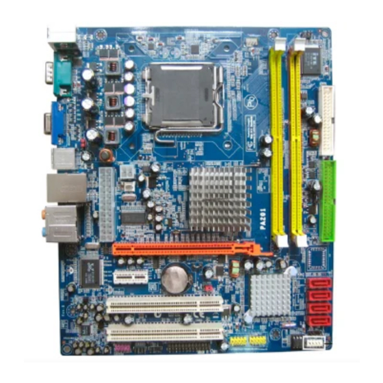
Page 4: Motherboard Components
Introducing the Motherboard Expansion Options • 1 PCI Express x16 Graphics Interface • 1 PCI Express x1 slot • 2 PCI slots (v2.3 compliant) • 1 IDE connector (supporting up to two IDE devices) • 1 Floppy disk drive interface •... - Page 5 Introducing the Motherboard Table of Motherboard Components LABEL COMPONENTS Socket LGA775 for Intel Core 2 Duo/Pentium 1.CPU Socket D/Pentium 4/Celeron D processors CPU cooling fan power connector 2.CPU_FAN1 240 pin DDRII SDRAM slots 3.DDRII1~2 Infrared header 4.IR1 Floppy disk drive connector 5.FDD1 Primary IDE connector 6.IDE1...
-
Page 6: Installing The Motherboard
Installing the Motherboard Chapter 2 Installing the Motherboard This chapter describes how to setup the jumpers on the motherboard as well as how to install the Processor and Cooler, Memory Modules, Power, IDE/SATA Hard Disk Drive or CD- ROM, Floppy Disk Drive, Expansion Card and other optional devices. While doing the installation, be careful in holding the components and following the installation procedures. -
Page 7: Install Processor And Cooler
Installing the Motherboard 2. Install Processor and Cooler Install the CPU components following instructions below. A. Unload the cap · Use thumb & forefinger to hold the lifting tab of the cap. · Lift the cap up and remove the cap completely from the socket. -
Page 8: Install Power
Installing the Motherboard 3. Install Power Refer to the motherboard image below for power connectors location. PWR1: Standard 24-pin ATX power supply connector Signal Name Signal Name VCC3 VCC3 VCC3 -12V VCC5 PS_ON VCC5 PWR-OK 5VSB VCC5 +12V VCC5 +12V VCC5 PWR1 VCC3... - Page 9 Installing the Motherboard necting 20/24-pin power cable Users please note that the 20-pin and 24-pin power cables can both be con- nected to the PWR1 connector. With either type of power cable, just align the power cable with the pin 1 of the PWR1 connector. However, using 20- pin power cable may cause the system to become unbootable or unstable because of insufficient electricity.
-
Page 10: Install Memory Modules
Installing the Motherboard 4. Install Memory Modules This motherboard accommodates two 240-pin unbuffered DIMMs and supports DDR2 667/ 533/400 DDR2 SDRAM. You must install at least one module in any of the two slots. Each module can be installed with 1 GB of memory; the total memory capacity is 2 GB. Do not remove any memory module from its antistatic packaging until you are ready to install it on the motherboard. -
Page 11: Install A Hard Disk Drive/Cd-Rom/Sata Hard Drive
Installing the Motherboard 5. Install a Hard Disk Drive/CD-ROM/SATA Hard Drive This section describes how to install devices as a hard disk drive and a CD-ROM drive to an IDE connector or SATA connector. About IDE Connector This motherboard has one IDE channel interface. An IDE ribbon cable supporting two IDE devices is bundled with the motherboard. -
Page 12: Install A Floppy Diskette Drive
Installing the Motherboard Install Serial ATA Hard Drives 6. Install a Floppy Diskette Drive The motherboard has a floppy diskette drive (FDD1) interface and ships with a diskette drive ribbon cable (optional) that supports one or two floppy diskette drives. You must orient the cable connector so that the pin 1 (color) edge of the cable corresponds to the pin 1 of the I/O port connector. -
Page 13: Install Add-On Cards
Installing the Motherboard 7. Install Add-on Cards The slots on this motherboard are designed to hold expansion cards and connect them to the system bus. Refer to following motherboard image for the add-on cards slots location. PCI-E1 Slot The PCI Express x16 slot is used to install an external PCI Express interface graphics card. - Page 14 Installing the Motherboard Follow these instructions to install an add-on card: 1 Remove a blanking plate from the system case corresponding to the slot you are going to use. 2 Install the edge connector of the add-on card into the expansion slot. Ensure that the edge connector is correctly seated in the slot.
-
Page 15: Install Internal Headers And Connectors
Installing the Motherboard 8. Install Internal Headers and Connectors Refer to the following motherboard image for the location of the CPU/system cooling FAN power connector and the internal speaker header. CPU_FAN1: CPU cooling FAN power connector Signal Name Function System Ground +12V Power +12V FAN_SENSE... - Page 16 Installing the Motherboard Refer to the following motherboard image for the location of front panel switch/LED header. PANEL1: Front panel switch/LED header The front panel header (PANEL1) provides a standard set of switch and LED headers com- monly found on ATX or Micro ATX cases. Signal Function Signal...
- Page 17 Installing the Motherboard Refer to the following motherboard image for the location of front panel audio header and SPDIF out header. F_AUDIO1: Front panel audio header This header allows the user to install auxiliary front-oriented microphone and 8-channel line-out ports for easier access. Signal Name Signal Name PORT-F L...
- Page 18 Installing the Motherboard Refer to the following motherboard image for the location of the analog audio input header and the onboard parallel port header. CD_IN1: Analog audio input header Function Signal Name CD IN L CD In left channel Ground Ground CD IN R CD In right channel...
- Page 19 Installing the Motherboard Refer to the following motherboard image for the location of the front panel USB headers. F_USB1~2: Front panel USB headers The front USB headers can be connected to the front-mounted ports for more USB interface peripherals. Signal Name Signal Name DATA- DATA-...
- Page 20 Installing the Motherboard Refer to the following motherboard image for the location of the infrared header. IR1: Infrared header The motherboard supports an Infrared (IR1) data port. Infrared ports allow the wireless exchange of information between your computer and similarly equipped devices such as printers, laptops, Personal Digital Assistants (PDAs), and other computers.
-
Page 21: Bios Setup
BIOS Setup Chapter 3 BIOS Setup When you power on the system, BIOS enters the Power-On Self Test (POST) routines. POST is a series of built-in diagnostics performed by the BIOS. After the POST routines are completed, the following message appears: Press DEL to enter SETUP Press the delete key to access the BIOS Setup Utility. -
Page 22: Standard Cmos Features
BIOS Setup Load Optimized Defaults Use this menu to install optimized defaults for all appropriate items in the Setup Utility. BIOS Security Features The menu lets you set or change the supervisor password and user password. Save & Exit Setup Save changes to CMOS and exit the setup. -
Page 23: Advanced Bios Features
BIOS Setup 3. Advanced BIOS Features This option defines advanced information about your system. CMOS Setup Utility - Copyright (C) 1985-2004, American Megatrends, Inc. Advanced BIOS Features CPU Configuration [Press Enter] Item Help 1st Boot Device [1st FLOPPY DRIVE] 2nd Boot Device [CD/DVD: SS-SONY DVD] 3rd Boot Device [Network: Realtek Bo]... - Page 24 BIOS Setup 1st/2nd/3rd Boot Device Use these three items to select the priority and order of the devices that your system searches for an operating system at start-up time. Removable Drives (Press Enter) Scroll to this item and press <Enter> to view the following screen: CMOS Setup Utility - Copyright (C) 1985-2004, American Megatrends, Inc.
-
Page 25: Advanced Chipset Features
BIOS Setup 4. Advanced Chipset Features These items define critical timing parameters of the motherboard. You should leave the items on this page at their default values unless you are very familiar with the technical specifications of your system hardware. If you change the values incorrectly, you may introduce fatal errors or recurring instability into your system. -
Page 26: Integrated Peripherals
BIOS Setup PCIE/VGA Configuration (Press Enter) Scroll to this item and press <Enter> to view the following screen: CMOS Setup Utility - Copyright (C) 1985-2004, American Megatrends, Inc. PCIE/VGA Configuration Item Help Init Display First [PCI Express X16] Share Memory Size [Enabled, 8MB] Select which graphics DVMT/FIXED Memory... - Page 27 BIOS Setup Onboard Devices Controller (Press Enter) Scroll to this item and press <Enter> to view the following screen: CMOS Setup Utility - Copyright (C) 1985-2004, American Megatrends, Inc. Onboard Devices Controller Item Help Onboard IDE Controller [Enabled] [Enabled] Onboard SATA Controller Enable or disable the integrated IDE controller...
-
Page 28: Power Management Setup
BIOS Setup 6. Power Management Setup This option lets you control system power management. CMOS Setup Utility - Copyright (C) 1985-2004, American Megatrends, Inc. Power Management Setup [S3 (STR)] Suspend mode Report Video on S3 Resume [No] Item Help USB Wakeup From S3 [Disabled] Restore on AC Power Loss [Power Off]... -
Page 29: Pc Health Status
BIOS Setup 7. PC Health Status On motherboards that support hardware monitoring, this menu lets you monitor the parameters for critical voltages, temperatures and fan speeds. CMOS Setup Utility - Copyright (C) 1985-2004, American Megatrends, Inc. PC Health Status Item Help Smart Fan Control [Disabled] CPU Temperature... -
Page 30: Using The Software Cd
Using the Software CD Chapter 4 Using the Software CD 1. About the Software CD The support software CD that is included in the motherboard package contains the drivers and utilities needed to properly run the bundled products. Besides, User’s Manual and Adobe Reader program are both provided for easier installation and setup of your motherboard. -
Page 31: Driver Disk Profile
Using the Software CD 3. Driver Disk Profile Click the button Driver Disk Profile, the screen will show all the drivers and tools available in this driver disk. The above screens are examples only. The screens and driver lists will be different according to the motherboard you are installing.
Need help?
Do you have a question about the 945GC1066 and is the answer not in the manual?
Questions and answers