
Subscribe to Our Youtube Channel
Related Manuals for Weishaupt WL10/2-C Z


Summary of Contents for Weishaupt WL10/2-C Z
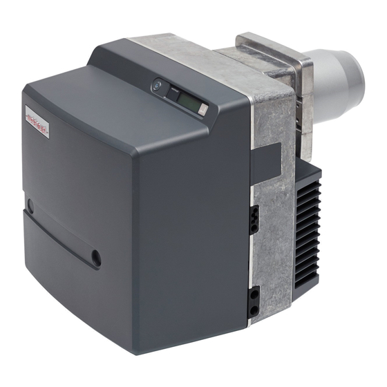
- Page 1 Installation and operating instructions 83055602 - 1/2002 Weishaupt oil burners WL10/2-C, vers. Z...
- Page 2 Conformity Certification to ISO/IEC Guide 22 Confirmed by: Max Weishaupt GmbH Address: Max Weishaupt Straße D-88475 Schwendi Product: Oil burner with fan Type: WL10/2-C, Vers. Z The product described above conform to Document No.: EN 267 EN 292 EN 50 081-1...
-
Page 3: Table Of Contents
Contents 1 General instructions 2 Safety instructions 3 Technical description 3.1 Permissible application 3.2 Basic function 4 Installation 4.1 Safety notes on installation 4.2 Delivery, transport and storage 4.3 Preparation for installation 4.4 Oil supply 4.5 Burner installation 4.6 Electrical connection 4.7 Nozzle selection 5 Commissioning and operation 5.1 Safety notes on initial commissioning... -
Page 4: General Instructions
DANGER Guarantee and liability Weishaupt will not accept liability or meet any guarantee claims for personal injury or damage to property arising as This symbol is used to mark instructions, a result of one or more of the causes below: which, if not followed, could result in life threatening electric shock. -
Page 5: Safety Instructions
2 Safety information Dangers when using the equipment Electrical safety Weishaupt products are manufactured in accordance with • Work on the electrical supply should be carried out by the relevant existing standards and guidelines and the a qualified electrician. recognised safety laws. However, improper use of the •... -
Page 6: Technical Description
3 Technical description 3.1 Permissible applications The Weishaupt oil burner WL10 is suitable for: Type designation: • heat exchangers complying with EN303-2 or DIN4702-1 • for warm water installations with intermittent or 10 /2 -C, vers. Z continuous run (combustion manager switches off once in 24hrs.) -
Page 7: Basic Function
3.2 Basic function Burner type Function schematic • Fully automatic oil atomising burner with fan • Two stage operation ➀ ➃ Digital combustion manager ➁ Main points: • Safety via internal fuse ➂ • Control and monitoring of all burner functions •... - Page 8 Oil pump AT2 45C Oil Pump AT2 45C • Pump for distillate oil EL • Two ratings ranges • Two integral pressure regulating valves One normally closed solenoid valve ➄ (stage 1); and • one normally open solenoid valve ➇ (stage 2) ➄...
-
Page 9: Installation
4 Installation 4.1 Safety notes on installation Electrically isolate the plant Prior to installation switch off the mains switch and the safety switch. Failure to comply could cause death or DANGER serious injury by electric shock. 4.2 Delivery, transportation and storage Check delivery Storage Check the delivery to see that it is complete and that there... - Page 10 Some local Codes of Practise may stipulate a shut off valve to stop the gravity flow of oil into the supply line during burner shut down. -weishaupt- recommend the use of a solenoid valve ➁ in ➀ ➀ the supply line. The solenoid valve must be slow closing so as to relieve any oil pressure back to the oil tank.
-
Page 11: Burner Installation
4.5 Burner installation Prepare heating appliance Refractory and drilling dimensions The diagram shows the refractory for a heating appliance without a cooled front. The refractory can be flat faced, or Refractory take a conical shape (≥ 60°). Refractory may not be required on boilers with water-cooled fronts, unless the Flange gasket manufacturer gives other instructions. -
Page 12: Electrical Connection
4.6 Electrical connection Check polarity of the connection plugs. Electrical connection Wiring diagram see Ch. 5.5. Connection to the mains supply should be carried out to the wiring diagram relevant for the type of unit. Notes for Austria Electrical isolation with a minimum of 3 mm contact gap, acting on all poles, must be fitted adjacent to the burner. -
Page 13: Commissioning And Operation
5 Commissioning and operation 5.1 Safety notes on initial commissioning The initial commissioning must only be carried out by the Furthermore the correct fusing of the circuits and the supplier, manufacturer or their appointed agent. At this measures for contact protection of electrical equipment time, all the control and safety equipment must be and of all wiring must be checked. -
Page 14: Initial Commissioning And Setting
5.3 Commissioning and setting Initial setting values for diffuser and air damper Generally, CO values between 12.0% and 13.0% are The burner can be preset for first commissioning using the achievable at the presetting stage. Presetting does not scale values for setting the diffuser and the air damper. replace the necessary flue gas measurements and The setting values are based on maximum combustion combustion optimisation. - Page 15 Full load (ST2) pre-setting: Set air damper Determine air damper setting using the full load curve in the diagram and set full load limit switch (ST2) accordingly. Partial load (ST1) pre-setting Determine air damper setting using the partial load curve in the diagram and set partial load auxiliary switch (ST1) accordingly.
-
Page 16: Shutdown Periods
Guide values for fan pressure into the mixing head Pressure guide values into the mixing head For the first commissioning the burner is set as per the setting values given in the diagrams, the given guide 5·5 values for the fan pressure into the mixing head will result, Full load 5·0 depending on the combustion chamber resistance of the... -
Page 17: Sequence Of Operation And Basic Wiring
5.5 Sequence of operations and wiring diagrams Sequence of operations diagram Boiler control Open partial load Demand partial Post purge solenoid valve load Pre-purge/pre- Partial load Full load solenoid ignition operation valve CLOSED Air damper on End of waiting Demand full load partial load time setting... - Page 18 Wiring diagram WL10/2-C, vers. Z W-FM10 interface...
-
Page 19: Operating The W-Fm10
5.6 Operating the W-FM 10 Function The illuminated push button integrated into the W-FM 10 Accidental operation of the push button for less than 1 has the following functions: second: • Resetting at burner lockout. Code stops flashing, combustion manager remains in the •... -
Page 20: Fault Conditions And Procedures For Rectification
6 Fault conditions and procedures for rectification The burner is found either out of operation, in lockout To avoid damage to the plant, do not reset the (signal lamp shows red) or burner operation is hindered burner more than twice. If the burner locks out (signal lamp flashes orange/red or green/red). - Page 21 Condition Cause Rectification Flame sensor Does not respond to flame Flame sensor defective Replace flame sensor Motor Does not run Capacitor defective Replace capacitor Oil pump seized Replace oil pump Motor defective Replace motor Signal lamp flashes orange / red Internal fuse F7 has tripped (Ch.
- Page 22 Condition Cause Rectification Combustion head Heavy soot deposits Defective nozzle Replace nozzle Burner incorrectly set Correct settings Amount of combustion air changed Reset burner Boiler room insufficiently ventilated Ensure sufficient boiler room ventilation as per local regulations Diffuser heavily soiled Burner incorrectly set Correct settings of mixing head (CH.
- Page 23 General operation problems Start up problems, burner does Incorrect setting of the ignition Correct setting (see Ch. 7.4) not start, no flame formation electrodes despite ignition and fuel supply Diffuser too close to front Check setting edge of flame tube If necessary adjust dimension S1(see Ch.
-
Page 24: Servicing
7 Servicing 7.1 Safety notes on servicing Failure to carry out maintenance and service Qualified personnel work properly can have severe consequences, Only qualified and experienced personnel must carry out including the loss of life. Pay close attention to maintenance and service work. the following safety notes. -
Page 25: Removing And Refitting Nozzle
7.3 Removing and refitting nozzle Removal Changing the nozzle WL10/2-C 1. Remove burner and place into service position (see Ch. 4.5) 2. Remove ignition cables 3. Remove screw 4. Remove diffuser from the nozzle assembly 5. Remove nozzle When changing the nozzle support the nozzle assembly. -
Page 26: Setting The Mixing Head
7.5 Mixing head setting If the combustion head and the diffuser have heavy soot Setting the mixing head deposits, or are very oily internally, the combustion head settings must be checked. Dimension S1 (distance from the diffuser to the front edge of the flame tube) can only be checked when the burner is mounted onto a hinged boiler door. -
Page 27: Removing And Refitting Nozzle Assembly
7.6 Removing and refitting nozzle assembly 7.7 Removing and refitting housing cover... -
Page 28: Service Position
7.8 Service position 7.9 Removing and refitting oil pump, fan motor and fan wheel Screw accessible via hole in fan wheel. When fitting, the screw should sit in the recess of the motor shaft. -
Page 29: Cleaning Air Housing And Air Damper
7.10 Cleaning the air regulator housing and air damper 7.11 Removing and refitting air damper angle gear... -
Page 30: Removing And Refitting Oil Pump Filter
7.12 Removal and refitting oil pump filter 7.13 Replacing internal fuse (W-FM10) -
Page 31: Technical Data
8 Technical data 8.1 Burner equipment Burner Combustion Motor Servomotor Fan wheel Ignition unit Flame Oil pump type manager sensor WL10/2-C; W-FM10 ECK 03/F-2 STD 4.5 146x40 W-ZG01 QRB1B AT2 45C vers. Z 230V, 50Hz BO. 36/6-4NL 2870 r.p.m. 24V; 3·5W 0·13 kW;... -
Page 32: Dimensions
8.6 Dimensions Burner Dims in mm type WL10/2-C, vers. Z 140 345 27 476 398 51 330 165 353 270 165 99 150- 170 –weishaupt– Fixing dimensions to EN 226 8.7 Weight WL10/2-C, vers. Z Burner ______________________________approx. 14.0 kg... -
Page 33: Appendix
Appendix Content • Combustion analysis • Notes Combustion analysis For safe, economic and environmentally friendly operation Determination of flue gas losses of the plant, flue gas measurements are essential when The oxygen content of the undiluted flue gas and the commissioning. - Page 34 Notes...
- Page 35 Notes...
- Page 36 Weishaupt Thermo Condens These Units combine the technical innovations and operating efficiencies developed from over 1 million installations. Weishaupt Thermo Gas and Weishaupt Thermo Unit provide the ideals of complete heating centres for houses and appartments. Product and service are the complete...
Need help?
Do you have a question about the WL10/2-C Z and is the answer not in the manual?
Questions and answers