Table of Contents
Advertisement
Quick Links
GOS-6200 OSCILLOSCOPE
USER MANUAL
CONTENTS
1.
PRODUCT INTRODUCTION.................................................
1-1.Description.......................................................
1-2.Feature.............................................................
2.
TECHNICAL SPECIFICATIONS.............................. 4
3.
PRECAUTIONS BEFORE OPERATION......................
3-1.Unpacking the instrument......................................
3-2.Checking the Line Voltage.....................................
3-3.Environment.....................................................
3-4.Equipment Installation and Operation......................
3-5.CRT Intensity...................................................
3-6.Withstanding Voltage of Input Terminals..................
4.
PANEL INTRODUCTION.........................................
4-1.Front Panel.......................................................
4-2.Rear Panel........................................................
5.
OPERATION METHOD...........................................
5-1.Readout Display..................................................
5-2.Connecting Input Signals......................................
5-3.Adjustment and Checks.......................................
5-4.Function Check..................................................
5-5.Basic Operation...................................................
5-6.Measurement Application.....................................
6.
MAINTENANCE...................................................
6-1.Fuse Replacement...............................................
6-2.Line Voltage......................................................
6-3.Cleaning..........................................................
7.
BLOCK DIAGRAM................................................ 58
⎯ i ⎯
PAGE
1
1
2
8
8
8
9
9
9
9
10
12
34
36
36
38
39
41
43
52
56
56
56
57
GOS-6200 OSCILLOSCOPE
USER MANUAL
SAFETY TERMS AND SYMBOLS
These terms may appear in this manual or on the product:
WARNING. Warning statements identify condition or
practices that could result in injury or loss of life.
CAUTION. Caution statements identify conditions or
practices that could result in damage to this product or
other property.
The following symbols may appear in this manual or on the product:
DANGER
ATTENTION
High Voltage refer to Manual Conductor
⎯ ii ⎯
Protective
Earth(ground)
Terminal
Terminal
Advertisement
Table of Contents

Related Manuals for GW Instek GOS-6200


Summary of Contents for GW Instek GOS-6200
-
Page 1: Table Of Contents
GOS-6200 OSCILLOSCOPE GOS-6200 OSCILLOSCOPE USER MANUAL USER MANUAL CONTENTS PAGE SAFETY TERMS AND SYMBOLS PRODUCT INTRODUCTION..........1-1.Description………………………………………………. These terms may appear in this manual or on the product: 1-2.Feature…………………………………………………..TECHNICAL SPECIFICATIONS………………………… 4 WARNING. Warning statements identify condition or PRECAUTIONS BEFORE OPERATION…….…………... - Page 2 GOS-6200 OSCILLOSCOPE GOS-6200 OSCILLOSCOPE USER MANUAL USER MANUAL This cable/appliance should be protected by a suitably rated and FOR UNITED KINGDOM ONLY approved HBC mains fuse: refer to the rating information on the equipment and/or user instructions for details. As a guide, cable of 0.75mm...
-
Page 3: Product Introduction
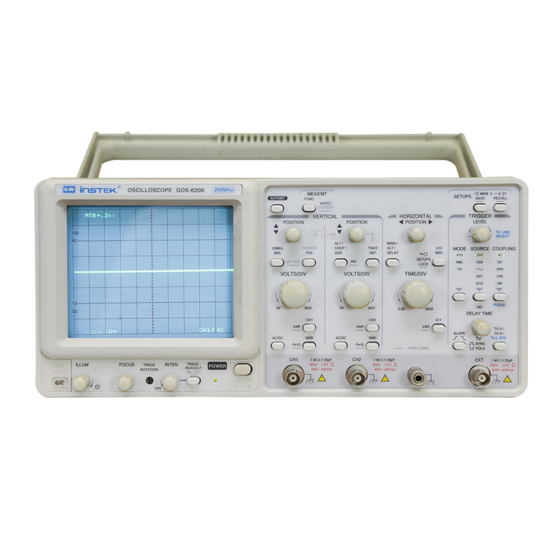
1-1. Description GOOD WILL INSTRUMENT CO., LTD. No. 7-1, Jhongsing Rd., Tucheng City, Taipei County 236, Taiwan The GOS-6200 is a 200MHz, two-channel, dual-sweep, portable oscilloscope GOOD WILL INSTRUMENT (SUZHOU) CO., LTD. No.69 Lushan Road, Suzhou New District Jiangsu, China. -
Page 4: 1-2.Feature
GOS-6200 OSCILLOSCOPE GOS-6200 OSCILLOSCOPE USER MANUAL USER MANUAL 1-2.Features 7) Trigger signal output Additionally, the oscilloscope offers several other features: The signal selected by the TRIGGER SOURCE is available. This 1) High intensity and internal graticule CRT output may be used to connect to a frequency counter or other The oscilloscope employs a high intensity 6-inch retangular type instrument. -
Page 5: Technical Specifications
GOS-6200 OSCILLOSCOPE GOS-6200 OSCILLOSCOPE USER MANUAL USER MANUAL 2.TECHNICAL SPECIFICATIONS Horizontal Modes MAIN(A), ALT, DELAY(B) 20ns~0.5sDIV, continuously variable Sensitivity 2mV~5V/DIV, 11 steps in 1-2-5 sequence A (main) Sweep Time (UNCAL) ±3% (5 DIV at the center display ) Sensitivity Accuracy... - Page 6 GOS-6200 OSCILLOSCOPE GOS-6200 OSCILLOSCOPE USER MANUAL USER MANUAL 6-inch rectangular type with internal graticule Type 0%, 10%, 90% and 100% markers. STORAGE 8 x 10 DIV (1 DIV = 1 cm) -10° to 70℃, 70%RH(maximum) TEMPERATURE Phosphor & HUMIDITY Accelerating Potential 14.5kV approx.
-
Page 7: Precautions Before Operation
GOS-6200 OSCILLOSCOPE GOS-6200 OSCILLOSCOPE USER MANUAL USER MANUAL 3.PRECAUTIONS BEFORE OPERATION 3-3.Environment 3-1.Unpacking the Oscilloscope The normal ambient temperature range of this instrument is from 0° to 40°C (32° to 104°F). To operate the instrument over this specific The product has been fully inspected and tested before shipping from the temperature range may cause damage to the circuits. -
Page 8: Panel Introduction
Scale Illumination control (ILLUM) and the Trace Rotation control, all other controls are electronically selected, and their functions and settings can therefore be stored. Front panel of GOS-6200 The front panel is subdivided into six sections: Display controls Vertical controls... -
Page 9: 4-1.Front Panel
GOS-6200 OSCILLOSCOPE GOS-6200 OSCILLOSCOPE USER MANUAL USER MANUAL 4-1.Front Panel (3).TRACE ROTATION Display controls The TRACE ROTATION is for aligning the horizontal trace in parallel The display controls adjust the on-screen appearance of the waveform and with graticule lines. This potentiometer can be adjusted with a small provide a probe compensation signal source. - Page 10 GOS-6200 OSCILLOSCOPE GOS-6200 OSCILLOSCOPE USER MANUAL USER MANUAL (7).20MHz BWL – Pushbutton with indicator LED. (11)TRACE SEP Briefly pressing the pushbutton, the bandwidth is reduced to approx. The instrument contains a trace separate function which is required in 20MHz, and the measurement is made by eliminating undesired high the alternate time base mode to separate the DELAY time base trace(s) frequency signal from the waveform.
- Page 11 GOS-6200 OSCILLOSCOPE GOS-6200 OSCILLOSCOPE USER MANUAL USER MANUAL (13)CH1 VOLTS/DIV. (17)CH1 AC/DC. (14)CH2 VOLTS/DIV– Control knob for channel 1/channel 2 has double (18)CH2 AC/DC function. Pressing the pushbutton briefly to switch over from AC (~ symbol) to Turning the knob clockwise to increase the sensitivity in 1-2-5 sequence DC (= symbol) input coupling.
- Page 12 GOS-6200 OSCILLOSCOPE GOS-6200 OSCILLOSCOPE USER MANUAL USER MANUAL Horizontal controls: (22)MAIN/ALT/DELAY— Pushbutton for time base mode selection. The horizontal controls select the time base operation mode and adjust the The instrument contains two-time base designated MAIN and DELAY. horizontal scale, position and magnification of the signal.
- Page 13 GOS-6200 OSCILLOSCOPE GOS-6200 OSCILLOSCOPE USER MANUAL USER MANUAL window segment decreases when the DELAY time coefficient is set to (25)X-Y-VAR – Pushbutton with double function. a lower value (higher time deflection speed). For better reading, the vertical position of the DELAY time base trace Set to X-Y mode to select three functions sequentially by pressing the position can be shifted (please note TRACE SEP (11)).
- Page 14 GOS-6200 OSCILLOSCOPE GOS-6200 OSCILLOSCOPE USER MANUAL USER MANUAL Trigger controls (26)MODE – Pushbutton and indicator LEDs. The trigger controls determine the sweep start timing for both signal and Pressing the pushbutton to select the trigger mode. The actual setting is dual trace operation.
- Page 15 GOS-6200 OSCILLOSCOPE GOS-6200 OSCILLOSCOPE USER MANUAL USER MANUAL (27)TRIGGER LEVEL/TV LINE SELECT—Control knobs Couple DC and all frequency components of a triggering signal to the TRIGGER LEVEL Turning the control knob causes a different trigger input setting trigger circuitry. (voltage), and set to a suitable position for the starting of triggered DC coupling is useful for most signals, especially for providing a sweep of the waveform.
- Page 16 GOS-6200 OSCILLOSCOPE GOS-6200 OSCILLOSCOPE USER MANUAL USER MANUAL (29)SOURCE—Pushbutton and associated LEDs. (30)HO-DELAY—Control knob with a double function and associated Pressing the pushbutton to select the trigger signal source or the X LED. signal for an X-Y operation. The actual setting is indicated in a LED The control knob has two different functions depending on the time and by the readout (“SOURCE”, slope, coupling).
- Page 17 GOS-6200 OSCILLOSCOPE GOS-6200 OSCILLOSCOPE USER MANUAL USER MANUAL (31)TV-V/TV-H/TV-STD—Pushbutton for video sync signal selection. (32)SLOPE ( )/TV SYNC POLA( )—Pushbutton for In the TV trigger mode, each time when the pushbutton of TV-V/TV- the triggering slope or video polarity selection.
- Page 18 GOS-6200 OSCILLOSCOPE GOS-6200 OSCILLOSCOPE USER MANUAL USER MANUAL (33)AUTOSET— (34) MEMO- 9 —SAVE/RECALL Pressing briefly the AUTOSET pushbutton to set the instrument to the The instrument contains 10 non-volatile memories, which can be used last time base mode of CH1, CH2 and DUAL.
- Page 19 GOS-6200 OSCILLOSCOPE GOS-6200 OSCILLOSCOPE USER MANUAL USER MANUAL △T Input connectors Time difference measurement. △T% Time difference percentage measurement. The input section is where the input signals are commonly connected to (5div=100% reference). the oscilloscope. 1/△T Frequency measurement. △θ Phase measurement.
-
Page 20: 4-2.Rear Panel
GOS-6200 OSCILLOSCOPE GOS-6200 OSCILLOSCOPE USER MANUAL USER MANUAL (39)EXT—This BNC socket is the external trigger signal input. (40)Line voltage selector and input fuse holder—Select power source In dual X-Y mode, signals at this input are used for the X deflection. -
Page 21: Operation Method
GOS-6200 OSCILLOSCOPE GOS-6200 OSCILLOSCOPE USER MANUAL USER MANUAL 5. OPERATION METHOD This section contains basic operation information and techniques that should be considered before proceeding any measurement. As for the location and function of instrument controls, connectors, and indicators, refer to the “Instruction of Front Panel and Rear Panel” of this manual. -
Page 22: 5-2.Connecting Input Signals
GOS-6200 OSCILLOSCOPE GOS-6200 OSCILLOSCOPE USER MANUAL USER MANUAL 5-2.Connecting Input Signals 5-3.Adjustments and checks Grounding Trace Rotation Adjustment The most reliable signal measurements are made when the oscilloscope Normally, when the trace is in parallel with the center horizontal graticule and the unit under test are connected by a common reference (ground lead) line, there will be no need to adjust the TRACE ROTATION. -
Page 23: 5-4.Function Check
GOS-6200 OSCILLOSCOPE GOS-6200 OSCILLOSCOPE USER MANUAL USER MANUAL 5-4.Function Check 7. Observe the displayed waveform and compare them with the waveforms When you start to check the operation of your oscilloscope, proceed the shown in figure 5-2. If either probe needs to be adjusted, proceed the following instruction: step 8. -
Page 24: 5-5.Basic Operation
GOS-6200 OSCILLOSCOPE GOS-6200 OSCILLOSCOPE USER MANUAL USER MANUAL 5-5.Basic Operation 4. Set both CH1 and CH2 COUPLING to GND. 5. Use the CH1 and CH2 POSITION controls to align both traces on the Displaying CH1 or CH2 center graticule. To display the signal from a signal channel, pressing briefly the CH1 or 6. - Page 25 GOS-6200 OSCILLOSCOPE GOS-6200 OSCILLOSCOPE USER MANUAL USER MANUAL Displaying the sum or difference of CH1 and CH2 Comparing Frequency and phase (Single X-Y Operation) To display the algebraic sum or difference of CH1 and CH2, proceed the To compare the frequency and phase between two signals by using the following steps: X-Y mode.
- Page 26 GOS-6200 OSCILLOSCOPE GOS-6200 OSCILLOSCOPE USER MANUAL USER MANUAL Setting up Dual X-Y Operation To use the oscilloscope in the dual X-Y mode, proceed the following steps: 2. Set the MAIN/ALT/DELAY button to ALT mode, and set the time 1. Connect the horizontal or X-axis signal to the EXT (X) input.
- Page 27 GOS-6200 OSCILLOSCOPE GOS-6200 OSCILLOSCOPE USER MANUAL USER MANUAL Magnifying Waveform Events Use the ×10 MAG pushbutton to view small portions of a waveform as which is too far back from the starting point to view by using the TIME/DIV control. To use the ×10 MAG button, proceed the following steps: 1.
- Page 28 GOS-6200 OSCILLOSCOPE GOS-6200 OSCILLOSCOPE USER MANUAL USER MANUAL TV-V/TV-H/TV-STD pushbutton to set TV-H triggering. To trigger the The polarity of the synchronization pulse is critical for the slope selection. oscilloscope at the horizontal (signal line), press the TV-V/TV-H/TV- The figure 5-13(a) and 5-13(b) shows the examples of TV polarity STD pushbutton to set TV-L triggering.
-
Page 29: 5-6.Measurement Application
GOS-6200 OSCILLOSCOPE GOS-6200 OSCILLOSCOPE USER MANUAL USER MANUAL 5-6.Measurement Application Figure 5-14: Cursor Measurement (a).Typical △V (Voltage difference) for AC The oscilloscope has a cursor measurement system for making accurate, direct-readout voltage, time, frequency and phase measurements. The voltage. measurements described in this section are examples of typical When both CH1 and CH2 are turned on, the measurement value of CH1( △... - Page 30 GOS-6200 OSCILLOSCOPE GOS-6200 OSCILLOSCOPE USER MANUAL USER MANUAL (g).Typical △ Θ cursor function for phase 1. Set the VOLTS/DIV and VAR controls to provide an exact five- division vertical display. measurement. 2. Use the vertical POSITION control to control the negative amplitude...
-
Page 31: Maintenance
GOS-6200 OSCILLOSCOPE GOS-6200 OSCILLOSCOPE USER MANUAL USER MANUAL 6-3.Cleaning 6.MAINTENENCE To clean the oscilloscope, use a soft cloth dampened in a solution of mild The following instructions are executed by qualified personnel only. To avoid detergent and water. Do not spray cleaner directly onto the oscilloscope electrical shock, do not perform any servicing other than the operating because it may leak into the cabinet and cause damage. -
Page 32: Block Diagram
GOS-6200 OSCILLOSCOPE USER MANUAL 7.Block Diagram ⎯ 58 ⎯...
Need help?
Do you have a question about the GOS-6200 and is the answer not in the manual?
Questions and answers