Advertisement
Quick Links
深圳鼎华科技发展有限公司
Shenzhen Dinghua technology Development Co.,Ltd
DH-A2E BGA Rework Station Manual
Add:4th Floor, Building 6B, Shengzuozhi Industrial Zone, Road Xinyu,
Xinqiao, Shajing, Bao'an area, Shenzhen, China
Website:
www.sinobga.com
Tel: +86-755-29091633 29091833
Fax: +86-755-29091622
E-mail:Service@dinghua-bga.com
1
Advertisement

Related Manuals for Dinghua DH-A2E BGA


Summary of Contents for Dinghua DH-A2E BGA
- Page 1 深圳鼎华科技发展有限公司 Shenzhen Dinghua technology Development Co.,Ltd DH-A2E BGA Rework Station Manual Add:4th Floor, Building 6B, Shengzuozhi Industrial Zone, Road Xinyu, Xinqiao, Shajing, Bao'an area, Shenzhen, China Website: www.sinobga.com Tel: +86-755-29091633 29091833 Fax: +86-755-29091622 E-mail:Service@dinghua-bga.com...
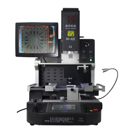
- Page 2 Contents A Company Profile B Installation 1) Installation 2) Power supply C Safety Precaution D Structures and Specifications 1) Structures 2) Functions 3) Main parameters E Setting F Operations G Usage of external couple H Usual temperature reference 1) Welding of lead BGA 2) Welding of lead-free BGA I Precautions Attach: Packing list...
- Page 3 “Research as basis, Quality as core, Service as guarantee” . Our goal: “Professional equipment, quality and service” To ensure the quality, Dinghua was the first to pass UL、E-MARK、CCC、FCC、CE ROHS certificates. Meanwhile, to improve and perfect the quality system, Dinghua has passed ISO、GMP、FCCA、C-TPAT on-site audit certification.
- Page 4 6.Prohibit Placing heavy objects on top of the touch screen 7.Without the influence of air-conditioners, heaters and fans 8.Reserved for 30cm to move and rotate around the upper for the back of rework station (B)Power supply INPUT :220AV±10% 50/60HZ (C).Safety Precautions 1.Do not use fans or other devices directly to the repair station hair when it works, otherwise it will lead to negative differential heating plate surface , burn the workpiece 2.When the machine is on working, high-temperature heating zone can not be any...
- Page 5 (B.)Functions Name Usage How to use The upper automatic Top heater heating structure Fine tune the BGA Rotate the micrometer Angle fine tune angle Positioning the BGA Laser chip Control the hot air Top heater hot air nozzle more evenly LED lamp Lighting when...
- Page 6 working Bottom heater hot air Control the hot air nozzle more evenly Preheating the PCB IR preheating zone board Control the IR heating IR preheater controller area according the Turn on/off the switch PCB board Adjust axis Workbench X axis fine Rotate micrometer tune workbench...
- Page 7 of the LED light on the lens Touch screen Operating the machine Total Power 5200W Top heater 1200W 2 nd:1200W 3 rd:2700W (Plus large fever area to adapt to all kinds of P Bottom heater board) power AC220V±10% 50/60Hz Dimensions L600×W700×H850 mm V-groove, PCB support can be adjusted in X direction with external universal Positioning...
- Page 8 5. Various sizes of BGA alloy nozzles, which can be adjusted 360 degree for easily installation and replacement. Three temperature areas can independently heat and they are multiple temperature control, which can ensure best integration of different temperature areas. Heating temperature, time, slope, cooling and vacuum can all be set in the human-machine interface.
- Page 9 Picture 1 2.Click on , it will shows as follow Picture 2 3. Click the input box, it will appear as follow:...
- Page 10 Picture 3 4.Input the password (the default password is 8888) The working interface will appear as follow Picture 5 The introduction of main working interface : Starting working : the status of the machine now. and it will show” heating” in the heating process : this is the optical align distance : this the soldering distance...
- Page 11 Soldering and Position : This is for keeping the constant temperature : Stopping button : Control the upper, bottom and air-flow cooling fan, Click it, it will become , all of the fans turn on : Show the name of working profile : Show the rest time of constant temperature : Indicate temperature detected by the outer temperature sensor 1 The color of curve is Baby blue...
- Page 12 Picture 6 The temperature rate is usual at 3 degrees per second.The upper/bottom and infrared temperature zones can set up to 8 heating temperatures and 8 constant times,the parameters can be modified in the current curve system, but they are not going to be saved in the procedure If saving is needed, please refer to the following procedure “17”!If the profile is not suitable for the required welding temperature, please click , return to the main interface...
- Page 13 is the distance for optical align,the distance is from the BGA chip(which is being picked up) to the CCD camera, we usually set it 20. Click it, the interface will appear as follow Picture 7 In this interface, you can modify and save temperature profiles Users can set the heating time, constant time and temperature rate accordingly, button to choose the relevant parameter as follow,...
- Page 14 Picture 8 If it is necessary to input new parameters, click input field where need to modify, it will appear like the picture; Picture 9...
- Page 15 Input the parameter, press Then click after setting these three temperature zones, then these parameters will be saved in the system with the displayed name Besides, you can click the input field below to change the curve’s name, the dialogue will appear as follow Picture 10 You can also click to modify the curve name...
- Page 16 indicates that the machine goes into constant state, three group of heating output of the whole machine will operate with current temperature, until click “keep on” , the machine come back the normal heating state setting has been done with all parameters set when the machine leaved the factory, users have no need to modify This machine can log monitor rotate speed of cooling fan against hot wind from up and down, and you can also set the lowest rotate speed When it appears that fan stops...
- Page 17 1. Camera: The indicator will turn green when CCD Camera in the oringal. 2. Suction: The indicator is on green, the top heater is on stand by. 3. Protect: The indicator is on green, when the top heater inductive switch in on. 4.
- Page 18 This machine could apply to in soldering and desoldering the BGA chip 1. Preheating: Preheating before reworking, the temperature of constant temperature oven is set at 80 ℃ -100 ℃, for 4-8 hours to demoist the PCBA ,to prevent the explose during reworking 2.
- Page 19 3).The upper sucker will go down to )welding position as set in “picture 6” to pick up the BGA chip, and goes up the Optic position set in “picture 6” 4).The optical CCD camera will go out right away for alignment, the BGA tin ball and welding pad will be displayed on the monitor screen, you can check images of tin balls on the screen through the adjusting angle handle--X axis,Y axis and angle axis,the tin ball and PCB’s pad must be coincided completely on the screen...
- Page 20 When the ball reached the melting point, it is in a liquid state , if too long or too high temperature and pressure, it will destroy surface tension of solder balls and the supporting role, resulting in short-circuit phenomenon when reflows, the chips fall entirely on the PCB pads the , so we need to appropriately reduce the heating section of the third and fourth soldering temperature and time , or reduce the bottom of the preheat temperature...
- Page 21 Picture sixteen c Adjust the position of PCB board so that the ready to be heated parts is under the upper warm wind nozzle (Like picture sixteen) d Adjust the adjusting knob of head blow-dryer up and down so that the upper warm wind nozzle is 2-3mm higher than the surface of PCB board e Choose the touch screen interface (like picture five), click “start”, then the upper heater begin to heat...
- Page 22 measuring interface (image 17) will display the current upper temperature (in red) and outer temperature (in light blue) as 2 curve lines 5 Red curve displays temperature measured by galvanic couple inside the upper thermal fuse, light blue curve displays actual temperature measured by outer galvanic couple, the smaller the deviation between the red curve and the light blue curve is, means the nearer between the temperature of actually heating part and target temperature If it is contrary, means the...
- Page 23 I Please according to relevant correct operation; avoid to be burnt by high temperature! Use the same theory, paste the outer galvanic couple on the bottom of PCB board, that is the right above of bottom dryer, only reserve lower heating (turn off the upper heating), can measure and correct the accuracy of lower heater 9 Statement: Turn off the upper heater (set the data relevant to upper heater to...
- Page 24 Upper rate Lower temperature Constant time Lower rate Infrared temperature Constant time Infrared rate 38*38 BGA welding temperature setting Upper temperature Constant time Upper rate Lower temperature Constant time Lower rate Infrared temperature Constant time...
- Page 25 Infrared rate 31*31 BGA welding temperature setting Upper temperature Constant time Upper rate Lower temperature Constant time Lower rate Infrared temperature Constant time Infrared rate Above reference temperature are for the leaded products Lead-free temperature curve welding 41*41 BGA welding temperature setting Upper temperature Constant time...
- Page 26 Constant time Infrared rate 38*38 BGA welding temperature setting Upper temperature Constant time Upper rate Lower temperature Constant time Lower rate Infrared temperature Constant time Infrared rate 31*31 BGA welding temperature setting Upper temperature Constant time Upper rate Lower temperature Constant time Lower rate...
- Page 27 Infrared temperature Constant time Infrared rate Above reference temperature are for the lead-free products Above are Intel lead-free BGA temperature references If you want to dismounting the BGA chip, the cooling temperature can be set 0 I Announcements of BGA operation 1.After opening the power, firstly you should check whether the upper and bottom hot air nozzles have cold wind If not, starting the power is strictly prohibited, or the heaters will be burnt The bottom infrared heating areas are all...
- Page 28 board will be damaged 6.The machine surface needs to be clean at regular time, especially the infrared heating board Avoid the dirt stay on the board, because the dirt can lead to heat radiation unnormally, bad welding quality and shorten the using time of infrared heating element If the heating element was burn out because of this, our company is not responsible for it and no free charge!
- Page 29 HD display screen Suction nozzle Instruction manual DH-A2E COPY Hot-air nozzle Upper nozzle:31*31 、 38*38、 41*41 Bottom nozzle: 55*55、 34*34 Shaped clip Plum knob Supporting screw Temperature sensor...
Need help?
Do you have a question about the DH-A2E BGA and is the answer not in the manual?
Questions and answers