Advertisement
Quick Links
深圳鼎华科技发展有限公司
Shenzhen Dinghua technology Development Co.,Ltd
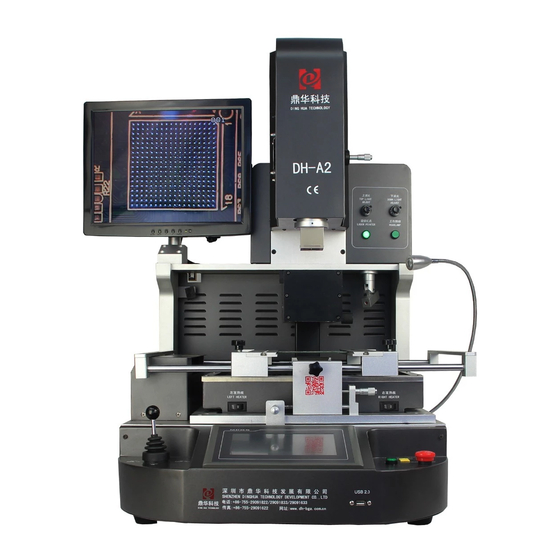
DH-A2 BGA Rework Station Manual
ADD: 4th Floor,Buliding 6B, Shengzuozhi Technoilogy Park,Bao'an District,
Xinqiao,Shajing Town, Bao'an District, Shenzhen, Guangdong,China
Tel: 0755-29091633/29091833
Fax: 0755-29091622
Website: www.sinobga.com
E-mail:dh-smt@hotmail.com
1
Advertisement

Related Manuals for Dinghua DH-A2


Summary of Contents for Dinghua DH-A2
- Page 1 深圳鼎华科技发展有限公司 Shenzhen Dinghua technology Development Co.,Ltd DH-A2 BGA Rework Station Manual ADD: 4th Floor,Buliding 6B, Shengzuozhi Technoilogy Park,Bao’an District, Xinqiao,Shajing Town, Bao’an District, Shenzhen, Guangdong,China Tel: 0755-29091633/29091833 Fax: 0755-29091622 Website: www.sinobga.com E-mail:dh-smt@hotmail.com...
- Page 2 Contents A Company Profile B Installation 1) Installation 2) Power supply C Safety Precaution D Structures and Specifications 1) Structures 2) Functions 3) Main parameters E Setting F Operations G Usage of external couple H Usual temperature reference 1) Welding of lead BGA 2) Welding of lead-free BGA I Precautions Attach: Packing list...
- Page 3 “Research as basis, Quality as core, Service as guarantee” . Our goal: “Professional equipment, quality and service” To ensure the quality, Dinghua was the first to pass UL、E-MARK、CCC、FCC、CE ROHS certificates. Meanwhile, to improve and perfect the quality system, Dinghua has passed ISO、GMP、FCCA、C-TPAT on-site audit certification.
- Page 4 6.Prohibit Placing heavy objects on top of the touch screen 7.Without the influence of air-conditioners, heaters and fans 8.Reserved for 30cm to move and rotate around the upper for the back of rework station (B)Power supply INPUT :220AV±10% 50/60HZ (C).Safety Precautions 1.Do not use fans or other devices directly to the repair station hair when it works, otherwise it will lead to negative differential heating plate surface , burn the workpiece 2.When the machine is on working, high-temperature heating zone can not be any...
- Page 5 Top heater Screen Display Top heater hot air nozzle CCD light adjusting Laser Cross Cooling fan LED lamp Bottom hot air nozzle Clip controller IR preheating area IR controller Workbench X axis fine tune Bottom nozzle height controller Work bench Y axis fine tune Outer temp.
- Page 6 Control the IR heating IR preheater controller area according the Turn on/off the switch PCB board Adjust axis Workbench X axis fine Rotate micrometer tune workbench Adjust axis WorkbenchY axis fine Rotate micrometer tune workbench Control the distance Bottom heater height between the bottom Rotate the knob...
- Page 7 Total Power Total Power 5200W 5200W Top heater Top heater 1200W 1200W 2 nd:1200W 3 rd:2700W (Plus large fever area to adapt to all kinds of P 2 nd:1200W 3 rd:2700W (Plus large fever area to adapt to all kinds of P Bottom heater Bottom heater board)
- Page 8 Collocating with sound control "early warning" function. It can warn workers to make some relative preparation 5-10 seconds before the completion of uninstalling or welding. Cooling system will start after vertical wind stopped heating. When the temperature drops to normal temperature, the cooling process will stop automatically, so that the machine will not be aging after temperature heated up.
- Page 9 Picture 2 3. Click the input box, it will appear as follow: Picture 3 4.Input the password (the default password is 8888) The working interface will appear as follow...
- Page 10 Picture 5 The introduction of main working interface : Starting working : the status of the machine now. and it will show” heating” in the heating process this is the optical align distance this the soldering distance the status for the work, click here,it will has 3 function, Dismount, Soldering, Mounting : This is for keeping the temperature constant...
- Page 11 : Stopping button : Control the upper.bottom and overflow cooling fan, Click it, it will become , all of the fans turn on : Show the name of working profile : Show the rest time of constant temperature : Indicate temperature detected by the outer temperature sensor 1 The color of curve is Baby blue : Indicate the practical temperature of upper heater The color of curve is : Indicate the practical temperature of lower heater The color of curve is...
- Page 12 Picture 6 The temperature rate is usual at 3 degree per second The upper.bottom and infrared temperature zones can set up to 6 increase temperature and 6 constant temperature You can modify the parameters in the current curve system, but they are not going to be saved in the procedure If saving is needed, please refer to the following procedure 17!...
- Page 13 is the distance for optical align,the distance is from the bga chip to the CCD camera,we usally set it 20 Click it, the interface will appear as follow Picture 7 In this interface, you can modify and save temperature profiles Users can set the heating time, constant time and temperature rate accordingly, button to choose the relevant parameter as follow,...
- Page 14 Picture 8 If it is necessary to input new parameters, click the box where need to modify, it will appear like the picture; Picture 9...
- Page 15 Input the parameter, press Then click after setting these three temperature zones, then these parameters will be saved in the system with the displayed name Besides, you can click the box below to change the curve’s name, the dialogue will appear as follow Picture 10 You can also click to modify the curve name...
- Page 16 constant state, three group of heating output of the whole machine will operate with current temperature, until click OFF again, the machine come back the normal heating state setting has been done with all parameters set when the machine leaves factory, users have no need to modify This machine can log monitor rotate speed of cooling fan against hot wind from up and down, and you can also set the lowest rotate speed When it appears that fan stops or fan rotate speed lower than it is set during heating, when the upper and bottom...
- Page 17 1. Camera: The indicator will turn green when CCD Camera in the oringal. 2. Suction: The indicator is on green, the top heater is on stand by. 3. Protect: The indicator is on green, when the top heater inductive switch in on. 4.
- Page 18 (F) Operations: This machine could apply to in soldering and desoldering the BGA chip 1. Preheating: Preheating before reworking, the temperature of constant temperature oven is set at 80 ℃ -100 ℃, for 4-8 hours to demoist the PCBA ,to prevent the explose during reworking 2.
- Page 19 2).Select the proper profile, choose the mouting model Then click 3).The upper sucker will goes down to welding position as settled in picture 6 to pick up the BGA chip, and goes up the Optic position settled in picture 6 4).Pull the optical lens out, the BGA tin ball and welding pad will be displayed on the screen You can check images of tin balls on the screen through the adjusting angle handle.X axis.Y axis The tin ball and PCB welding position must be coincide...
- Page 20 Because of counterpoint by hand will cause deviation between chip and welding plate, surface tension of tin ball will have a process of automatic correction between BGA chip and welding pad Once heating, BGA falls not evenly, which will cause that the chip drops not evenly It will cause the phenomenon of missing weld and false weld if stop reflowing at this time, the chip will not fall normally So it is necessary for you to extend heating time of third .forth temperature zones or add the bottom pre-heating...
- Page 21 Picture fifteen Picture sixteen c Adjust the position of PCB board so that the ready to be heated parts is under the upper warm wind nozzle (Like picture sixteen) d Adjust the adjusting knob of head blow-dryer up and down so that the upper warm wind nozzle is 2-3mm higher than the surface of PCB board e Choose the touch screen interface (like picture five), click “start”, then the upper heater begin to heat...
- Page 22 1 Set upper temperature/time/speed rate and so on (upper heater correction) 2 Suggest that do the correction on abandoned circuit, avoid damaging the circuit and components on it 3 Carry out above process step (Three), install outer galvanic couple well, and center the galvanic couple under the top head blow-dryer 4 Turn off the bottom heating process (Set the data relevant to bottom heating to be 0), back to interface as image 5, click "Start"...
- Page 23 measuring temperature F After adjustment, you should fix the detector, avoid the detector from impacting the machine measuring temperature when shaking G Adjustment method in this example only apply to the state that when these two curves move in parallel and uniform deviation, useless when temperature up and down in disorder H Location of galvanic couple inside the upper blow-dryer: take down the blow-dryer, cover in the couple 2-3cm away from the blow-dryer...
- Page 24 H Usual temperature parameters Lead temperature curve welding 41*41 BGA welding temperature setting Upper temperature Constant time Upper rate Lower temperature Constant time Lower rate Infrared temperature Constant time Infrared rate 38*38 BGA welding temperature setting Upper temperature Constant time Upper rate...
- Page 25 Lower temperature Constant time Lower rate Infrared temperature Constant time Infrared rate 31*31 BGA welding temperature setting Upper temperature Constant time Upper rate Lower temperature Constant time Lower rate Infrared temperature Constant time Infrared rate Above reference temperature are for the leaded products Lead-free temperature curve welding 41*41 BGA welding temperature setting Upper...
- Page 26 Upper rate Lower temperature Constant time Lower rate Infrared temperature Constant time Infrared rate 38*38 BGA welding temperature setting Upper temperature Constant time Upper rate Lower temperature Constant time Lower rate Infrared temperature Constant time Infrared rate 31*31 BGA welding temperature setting Upper temperature...
- Page 27 Constant time Upper rate Lower temperature Constant time Lower rate Infrared temperature Constant time Infrared rate Above reference temperature are for the lead-free products Above are Intel lead-free BGA temperature references If you want to dismounting the BGA chip, the cooling temperature can be set 0 I Announcements of BGA operation 1.After opening the power, firstly you should check whether the upper and bottom hot air nozzles have cold wind If not, starting the power is strictly...
- Page 28 a cold wind Then elevate the upper heater, make the gap has 3-5mm space between the bottom of nozzle and the upper surface of BGA chip and keep cooling for 30-40 seconds, or move away the main heater after the starting light is off, finally take away the PCB board from the support 5.Before installation of BGA, it is necessary to check that if the PCB pad and BGA tin bead are all in good condition It is necessary to check the...
- Page 29 Packing List Item specification Unit BGA rework station DH-A2 HD display screen Suction nozzle Instruction manual DH-A2 COPY Hot-air nozzle Upper nozzle:31*31 、 38*38、 41*41 Bottom nozzle: 55*55、 34*34 Shaped clip Plum knob Supporting screw Temperature sensor...
Need help?
Do you have a question about the DH-A2 and is the answer not in the manual?
Questions and answers