Table of Contents
Advertisement
Quick Links
Hardware Installation Guide
Managed Fast/Gigabit Ethernet Switch
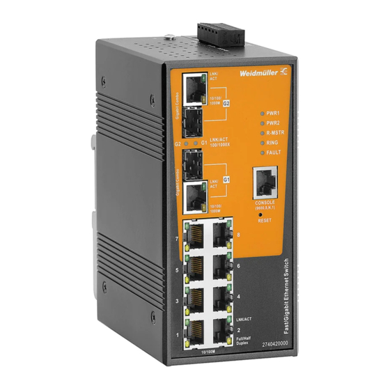
IE-SW-AL10M-8TX-2GC (Part No. 2740420000)
1.
Introduction
Ethernet Switches from Weidmüller are designed for industrial applications and fitted with a robust
housing. To ensure reliable, error-free operation, and to prevent damage or injury, please read the
operating instructions, all safety information provided in this document and any other safety
information that were supplied with the product.
2.
Safety notice
The device heats up during operation. Allow the unit to cool down or use protection
gloves when carrying out any work.
The device may only be connected to the supply voltage shown on the product label.
Higher voltage than specified will destroy the device.
The device must be supplied by a SELV source as defined in the Low Voltage
Directive 2014/35/EU and 2014/30/EU.
Installation, commissioning and maintenance may only be performed by qualified
electricians.
Observe the operating instructions.
Indoor use and pollution degree II, it must be wiped with a dry cloth for clean up
the device and label.
o Utilisation en intérieur et degré de pollution II, il faut l'essuyer avec un chiffon sec
pour nettoyer l'appareil et son étiquette.
Do not block air ventilation holes.
o Ne bouchez pas les orifices de ventilation.
If the equipment is used in a manner not specified by the manufacturer, the
protection provided by the equipment may be impaired.
o Si l'appareil est utilise d'une maniere non specifiee par le fabricant, la protection
qu'il apporte peut se voir diminuee.
Shall be mounted in the Industrial Control Panel and ambient temperature is not
exceed 75 degrees C.
o Doit être monté dans le panneau de commande industriel et la température
ambiante ne doit pas dépasser 75 degrés C.
Intended use: The device is intended for the realization of communication networks within an
industrial environment, it is intended to be used in a restricted access location. The device may
only be used within the scope of the specified technical data. The device is intended to be mounted
to a well-grounded mounting surface, such as a metal panel. Any other use may result in
unintentional malfunction and damage. Observing the documentation is part of the intended use.
Environmental conditions: This equipment is intended to be used in a restricted access location.
When planning the installation site make sure that the ambient temperature during operation will
not exceed the temperature given in the technical data. Also make sure that the air flow will not be
compromised by other devices. Ensure that the mounted and wired device is not exposed to any
mechanical stress.
FCC compliance: This device complies with part 15 of FCC Rules. Operation is subject to the
following two conditions: (1) This device may not cause harmful interference, and (2) this device
must accept any interference received, including interference that may cause undesired operation.
3.
Package Checklist
Your Ethernet Switch is shipped with the following items:
Ethernet Switch
Hardware Installation Guide (printed)
6-Pin Terminal connector
Serial console cable
Protective caps for RJ45 ports and SFP ports
1
4.
Panel Layouts
1.
Terminal block for power input PWR1/PWR2
and failure relay for power and port link loss
(output)
2.
Grounding screw / Frame ground (Note: The
shielding ground of the LAN port is
electrically connected to the grounding
screw)
3.
Power input LEDs (PWR1 / PWR2)
4.
Ring Master Status LED
5.
Ring Status LED
6.
Fault LED (PWR1/PWR2 fault or port link
loss)
7.
Serial Console Port (RS232)
8.
9.
Link/Activity LED 10/100Base-T(X) ports
10. Duplex mode LED 10/100Base-T(X) ports
(Amber = Full Duplex, OFF=Half Duplex, Off
= Collisions)
11. Article Number
12. Gigabit Combo Port (100/1000BASE-X SFP
slot / 10/100/1000BASE-T(X) port)
13. Link/Activity LEDs for Gigabit Combo Ports
G1/G2 (for an inserted SFP transceiver)
14. Link/Activity LED 10/100/1000BASE-T(X)
port
15. Port Speed LED 10/100/1000BASE-T(X) port
16. 10/100BASE-T(X) ports
17. DIN-rail kit
5.
DIN-Rail Mounting
Slide the switch onto a DIN-rail and make sure that the switch's Din-rail clip clicks into
the rail firmly.
STEP 1: Place the mounting clip from
above onto the mounting rail.
STEP 2: Press the device against the
DIN rail until the fastening element
engages on the mounting rail.
To remove the Ethernet Switch from
the DIN-rail pull down the latch with a
screwdriver then move the device
.
away from the DIN rail and lift it up
2
6.
Mounting Dimensions
7.
Grounding Ethernet Switch
ATTENTION
Grounding and wire routing help limit the effects of noise due to electromagnetic
interference (EMI).
the ground connection from the ground screw to the grounding surface prior to
connecting devices.
This product is intended to be mounted to a well-grounded mounting surface, such as
a metal panel.
The shielding ground of the RJ45 ports are electrically connected to the ground
connection (screw).
8.
Wiring Redundant Power Inputs and Fault Alarm Relay
The switch supports redundant power supply inputs and provides a fault alarm relay for
detecting the user-configurable failure events
Interruption of Power 1 or Power 2 and
Link Loss of Ethernet Ports.
Refer to illustration below for correct wiring.
Warning / Avertissement
Take into consideration the following guidelines before wiring the device
o Tenez compte des directrices suivantes avant de câbler l'appareil.
Terminal block is mating with Plug and suitable for 12-24AWG. Torque value 4.5 lb-in.
o Le bornier est compatible avec les connecteurs et convient pour 12-24AWG. Valeur
de couple 4,5 lb-in.
The temperature rating of the input connection cable should higher than 105°C.
o La température de service nominale du câble d'entrée doit être supérieure à 105 °C.
Supplied by SELV source evaluated by UL 61010-1 or 61010-2-201 power supply
only.
o Fourni par la source SELV évaluée uniquement par l'alimentation UL 61010-1 or
61010-2-201.
3
(units = mm)
Advertisement
Table of Contents

Related Manuals for Weidmüller IE-SW-AL10M-8TX-2GC


Summary of Contents for Weidmüller IE-SW-AL10M-8TX-2GC
- Page 1 (output) Managed Fast/Gigabit Ethernet Switch Grounding screw / Frame ground (Note: The shielding ground of the LAN port is electrically connected to the grounding IE-SW-AL10M-8TX-2GC (Part No. 2740420000) screw) Power input LEDs (PWR1 / PWR2) Ring Master Status LED Introduction...
- Page 2 IEEE 802.1D for STP (Spanning Tree protocol) Communication Connections IEEE 802.1w for RSTP (Rapid Spanning Tree protocol) IEEE 802.1s for MSTP (Multiple Spanning Tree Protocol) Switch IE-SW-AL10M-8TX-2GC is equipped with following communication interfaces: IEEE 802.1p for Class of Service 10. User Management 8 x 10/100BASE-T(X) ports IEEE 802.1Q for VLAN Tagging...
Need help?
Do you have a question about the IE-SW-AL10M-8TX-2GC and is the answer not in the manual?
Questions and answers