
Related Manuals for lassele LMI-650A


Summary of Contents for lassele LMI-650A
- Page 1 Installation and User’s Manual LMI-300A LMI-500A LMI-650A LMI-900A I512A-261 ver.202007_01...
-
Page 2: Table Of Contents
Table of Contents Freight Claim Procedure(Important) 1. Specifications .................. 4 1.1 Technical Specification 1.2 Product Dimensions 1.3 Accessories Included in the Unit 1.4 How to Determine Model Names and Serial Numbers 2. Installation & Operations Guide ..........11 2.1 Location Requirements 2.2 Installation Requirements 2.3 Electrical Requirements 2.4 Installation Checklist... -
Page 3: Freight Claim Procedure(Important)
Freight Claim Procedure(Important) Inspect Immediately This product has been carefully inspected and packed in accordance with the carrier’s packing specifications. Responsibility for safe delivery has been assumed by the carrier. If loss or damage occurs, you as the consignee must file a claim with the carrier and hold the container for carrier’s inspection. -
Page 4: Specifications
1. Specifications 1.1 Technical Specification ● Electrical & Refrigerant Data 300A Condenser Air Cooling Rated Voltage 115V/60Hz/1Ph 220-240V/50Hz/1Ph 220V/60Hz/1Ph Rated Ampere Compressor 115 V 37 LRA 6.35RLA 198-254V 18.6LRA 4.04RLA 187-254V 23.4LRA 4.46RLA Pump 115V 0.53FLA 59.9W 220-230V 0.16FLA 35.9W 220-230V 0.2FLA 41.3W 115V 0.68FLA 75.2W 220-230V 0.33FLA 56.9W... - Page 5 ● Electrical & Refrigerant Data 650A Condenser Air Cooling Rated Voltage 208-230V60Hz/1Ph 220-240V/50Hz/1Ph 220V/60Hz/1Ph Rated Ampere Compressor 198 ~ 264 V 24 LRA 5.9RLA 198 ~ 264 V 24 LRA 5.9RLA 208~230 V 29LRA 5.6 RLA Pump 230V/50Hz 0.29FLA 61.7W 230V/50Hz 0.29FLA 61.7W 220V/60Hz 0.28FLA 61.0W 220-230V 0.33FLA 56.9W...
- Page 6 ● Approximate Ice Production AT 70 °F / WT 50°F Model Rated Voltage AT 21 °C / WT 10°C 300A 115V/60Hz/1Ph 340 lbs/day (154 kg/day) 300A 220-240V/50Hz/1Ph 303 lbs/day (137 kg/day) 300A 220V/60Hz/1Ph 337 lbs/day (153 kg/day) 500A 115V/60Hz/1Ph 538 lbs/day (244 kg/day) 500A 220-240V/50Hz/1Ph 463 lbs/day (210 kg/day)
-
Page 7: Product Dimensions
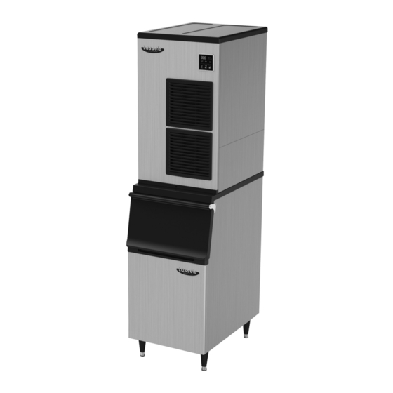
1.2 Product Dimensions ● 300A/500A FRONT SIDE REAR... - Page 8 ● 650A FRONT SIDE REAR...
- Page 9 ● 900A FRONT SIDE REAR...
-
Page 10: Accessories Included In The Unit
Earth Screw User Manual 1.4 How to Determine Model Names and Serial Numbers 1.4.1 Model names LMI - 300A Air - cooled L : Lassele M : Modular daily ice production in pound (U:Undercounter) I : Crescentice 1.4.2 Serial number... -
Page 11: Installation & Operations Guide
2. Installation & Operation Guide WARNING - The ice machine should be installed, following the local regulations of the country, state and region. - Read the manual thoroughly before installation. Incorrect installation may cause malfunction, or bodily injury and death. - Do not drop tools into the bin or the floor of the unit during installation. -
Page 12: Electrical Requirements
● Installation condition Condition Minimum Maximum °F Ambient Temperature °C °F Water temperature °C psig Water pressure 206.8 689.4 115V Voltage 220V 2.3 Electrical Requirements WARNING - Electrical wiring and grounding of the unit should be done in accordance to the applicable local, state and federallaws and regulations. - Page 13 2.3.3 Power Connection - Permanently connect : Wiring must be greater than 12AWG. - Cord connection: Refer to “1.1 Technical Specification” to check detailsof cable size requirements for the power supply. 2.4 Checklist before Installation - After unpacking, check the product appearance. If there is damage to the product, contact your place of purchase.
-
Page 14: How To Remove Machine Panel
2.5 How to Remove Panel To avoid any damage during installation, remove all panels. Remove them in the following order by referring to Fig 1. 1. Unscrew the bottom screw of the front panel and store it securely. 2. Remove the front panel by firmly grasping the bottom edge and pulling it up and away from the unit. -
Page 15: Bin Installation
2.6 Bin Installation WARNING - Check whether the ice machine and ice storage bin are compatible before installation. The ice machine and bin should be properly attached together. Install the bin in the following order by referring to Fig 2. 1. -
Page 16: Bin S/W Installation
2.7 Bin Switch Installation WARNING - Bin switch should be equipped before operating the ice machine. If it is not properly equipped, it might cause a breakdown or malfunction during ice storage. Install bin switch in the following order by referring to Fig 3. 1. -
Page 17: Water Supply & Drain Connections
2.8 Water Supply & Drain Connections WARNING - Installation of water supply and pipe system must be done in accordance to local, state and federal laws and regulations. - The ice machine is to be installed with adequate backflow protection to comply with applicable local, state and federal laws and regulations. - Page 18 ● Conditions for water supply and drainage Water Water connecting Size of Location temperature pressure fitting size connecting hose 7°C (45°F) Min. 30 psig(206.8kPa) Min. Water inlet 3/8” FPT ID 1/4” copper pipe(Min.) 100 psig(689.4kPa) Max. 32°C(90°F) Max. Drain 3/4” FPT ID 3/4”...
-
Page 19: Wire
2.9 Wire WARNING - Wiring must meet the local, state and federal standards where the machine is installed Improper wiring might cause electric shock, injury, fire or death. - Wiring must be done by a licensed electrician. - The machine requires an independent power supply. Check the nameplate for proper voltage and breaker/fuse size. -
Page 20: Final Check
2.10 Final Check WARNING After installation, make sure that all components, fixture, and thumbscrews are securely connected. Ensure that no impurities have fallen into the ice storage bin. (1) Are two manual valves opened? (2) Is ambient temperature of the installation area within the appropriate temperature range of 45-100°F(7-38°C)? (3) Is water temperature supplied to the installation area within the appropriate temperature range of 45-90°F (7-32°C)? -
Page 21: Operation
● When turning off the unit during a testrun, please do not attempt to re-operate until at least 3 minutes later to protect the compressor. ● If there is no water in the water tank, do not push"Wash" button to protect water pump seal. ●... -
Page 22: 7-Segments
3.3 7-segment Display Status Ready for cycle 1 = Water Supply Period .00 = Elapsed time (x 10 sec) 2 = Harvesting Period .00 = Elapsed time (min) 3 = Freezing Period .00 = Elapsed time (min) Drainage cycle Wash mode Ice machine is either cleaning or sanitizing. -
Page 23: Operation Cycle
3.4 Operation Cycle Ice machine is operated in accordance to the following process 1) Water supplying Cycle Once power is on, wate supply valve opens to fill the water tank with water. 2) Harvesting Cycle To remove ices made on the evaporator, water flow stops and it becomes hot. Then, ices are released from the evaporator to the storage container. -
Page 24: Error Codes
3.6 Error Code Code Problem Possible Cause Remarks Refrigerant leaked or pipe blocked Compressor not operating Fan motor not operating Freezing error (freezing time exceeds A/T : 45-100°F(7-38°C) 60 min) Ambient or water temperature too high W/T : 45-90°F(7-32°C) Voltage Voltage too high or too low 115V :100-130 V 220V :208-230 V... -
Page 25: Maintenance & Cleaning
4. Maintenance & Cleaning 4.1 Maintenance WARNING Ice machine must be maintained and cleaned based on schedule in this manual and the cleaning label attached on each unit. ● Maintenance Period Refer to the following table for guidance on the maintenance period. The maintenance period may be shorter than indicated depending on surrounding environment and hygiene regulations of the installation area. -
Page 26: Interior Cleaning & Sanitizing Procedure
4.2. Interior Cleaning / Sanitizing Procedure The ice machine should be cleaned and sanitized every six months. Depending on the installation condition, the machine may need more frequent cleaning and sanitizing. WARNING - Use a detergent and sanitizer for ice machine, and follow the directions of those products. -
Page 27: Sanitizing Procedure
11) After 5 minutes, remaining water will drain. 12) For 30 minutes, ice machine repeats steps 9-11. 13) Once cleaning cycle is completed, will be displayed on control board. 14) Press "Power" to turn off ice machine. 15) Disassemble water level sensor, ice guide, water supply hose, spray tube, and spray guide referring to 4.2.3 Modular Prdoduct Disassembly 16) Mix 5 oz. -
Page 28: Product Disassembly
4.2.3 Product Disassembly Top Insulator Top Cover Front Cover Front Insulator 1~2. Detach insulation top and front after detaching cover top and cover front. (Refer to 2.5 “Panel disassembly” for detailed instruction) Thumb Screw 3. Release thumb screw in the cabinet by referring to above image. - Page 29 Guide Ice Upper (only 300A) 4.- Grip the Guide Ice Upper and push it to the rear. - Pull it out through the left. - Pull out the Guide Ice Upper Ice Cover 5. - Release the bolt fixed on the Ice Cover. - Pull out the Ice Cover.
- Page 30 Water Cover Guide Ice 6. Pull out the parts to disassemble them in order of Water Cover and Guide Ice. Hose 7. Disassemble the clamps to detach the hoses...
- Page 31 Pump Motor 8. Unscrew the screws fixed on Level sensor and Pump motor and separate the Level sensor and Pump Motor. Spray Tube Supply Tube Spray Guide 9. Pull out the parts in order of Spray Tube , Supply Tube , and Spray Guide to disassemble them.
-
Page 32: Level Sensor Cleaning
4.3 Level Sensor Cleaning WARNING - Level sensor may not operate properly due to water condition or sediment inside of the sensor. For proper operation of Level sensor, clean the sediment inside of the sensor often. - Level Sensor should be cleaned at least once a month. (Recommended cleaning period can be shorter due to the condition of water. -
Page 33: Exterior Cleaning
4.4 Exterior Cleaning To prevent corrosion, clean oil or dust in outer surface with cleaning towel or neutral detergent. 4.5 Storage Container and Scoop Clean storage container interior and scoop with neutral detergent. Wash with clean water afterwards. Storage container is for ice only. Do not store any other material in the storage container. 4.6 Air Filter Dust in the filter may decrease function of ice machine. - Page 34 MEMO...
- Page 35 MEMO...
- Page 36 Manufacturer : DAEYEONG E&B ANSAN-SI, GYEONGGI-DO, REPUBLIC OF KOREA TEL.+82-31-491-1091 FAX. +82-31-491-0325 www.daeyeong.co.kr...
Need help?
Do you have a question about the LMI-650A and is the answer not in the manual?
Questions and answers