Table of Contents
Advertisement
Quick Links
Advertisement
Table of Contents

Related Manuals for Bosch WORCESTER GREENSTAR


Summary of Contents for Bosch WORCESTER GREENSTAR
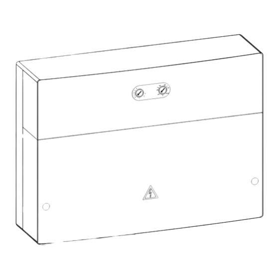
- Page 1 GREENSTAR WIRING CENTRE ma x 0010016703-001...
-
Page 2: Table Of Contents
Table of contents Table of contents Explanation of symbols and safety instructions Explanation of symbols Explanation of symbols and safety instructions ... 2 Explanation of symbols ......2 Warnings General safety instructions . -
Page 3: Product Information
Product Information H Intended use Product Information The module communicates via an EMS 2 interface In these instructions, the Greenstar Wiring Centre will be referred to as with other EMS 2-enabled BUS nodes, such as the module. Greenstar boilers. • The module controls the pump and motorised valves in –... -
Page 4: Scope Of Delivery
Product Information Scope of delivery Specifications Maximum power output • per connection • 400 W (high-efficiency (PZ1 ... PZ3) pumps permitted; max. 40 A/μs) • per connection • 230 V AC, max. 0.5 A (IZ1 ... IZ4) Set temperature sensor measuring range •... -
Page 5: Additional Accessories
Installation Additional accessories Installation For precise information regarding suitable accessories, refer to the Wall installation catalogue. ▶ Mount the module on a wall. • For a 3-way valve (Y-plan) system: – Circulating pump; connection to PZ3 – Y-plan diverter valve; connection to PZ1 and PZ2 –... -
Page 6: Electrical Connection
Installation Mounting rail installation Electrical connection ▶ Mount the module on a mounting rail. DANGER: Danger to life due to current! ▶ Secure the wires of all connected cables together. This can only be carried out by stripping back a short section of cable sheath or by using cable ties close to the terminals (... -
Page 7: Mains Voltage, Pump And Valve Connection (Mains Voltage Side)
Installation 3.2.2 Mains voltage, pump and valve connection Electrical connection – Step 1 (mains voltage side) 1. Remove grommets from the module. 2. Route cable through a grommet. 3. Remove plug from the socket. The allocation of the electrical connections depends on the system 4. - Page 8 Installation Electrical connection – Step 3 Electrical connection – Step 5 1. Remove grommets from the module. ▶ Secure cables connected in Steps 1-4 with the strain relief supplied. 2. Route cable through a grommet. 3. Remove plug from the socket. 4.
- Page 9 Installation Electrical connection – Step 7 Fitting the cover – Step 9 ▶ Secure cable connected in Step 6 with the strain relief supplied. 0 010 013 198-001 0 010 013 196-001 Fig. 19 Fitting the cover – Step 9 Fig.
-
Page 10: Connection Diagrams With System Schematics
II if the control thermostat is set at a lower manufacturer. temperature. The Worcester, Bosch Group customer service may be contacted on the telephone number on the back of these instructions. The Greenstar Wiring Centre must be wired as follows when installed in... - Page 11 Installation 3-way valve (Y-plan) system: VZ12 120/230 V AC N 43 N 14 II II 120/230 V AC 24 V IZ3 IZ4 120/230VAC 120/230VAC IN L IN L IN L IN 1 2 3 14 43 N 1 2 VZ12 230 V AC 230 V AC 0010016317-001 Fig.
- Page 12 Installation Two-port valve (S-plan) system: 120/230 V AC N 43 N 14 II II 120/230 V AC 24 V IZ2 IZ3 IZ4 120/230VAC 120/230VAC 1 2 3 IN L IN L IN L IN 230 V AC 230 V AC CZ1 CZ2 0010016318-001 Fig.
- Page 13 Installation 3 central heating circuits without electronic mixing valves: TZ4* TZ5* TZ6* PZ4* PZ5* PZ6* 120/230 V AC N 43 N 14 II II 120/230 V AC 24 V IZ2 IZ3 120/230VAC 120/230VAC IN L IN L IN L IN 1 2 3 N L S 230 V AC 230 V AC...
-
Page 14: Installing The System
Installation 2 heating circuits without electronic mixing valves and one domestic hot water cylinder circuit (S-plan Plus), with 2x Comfort II RF programmable room thermostats for load compensation: Greenstar 50 50 60 60 N 14 N 43 N 14 Wiring Centre 40 40 70 70 Primary Return... -
Page 15: Using The System
Commissioning Using the system The following are features of normal operation and ensure safe and efficient operation of the heating system: The receiver pairing mode lasts for up to one minute. • During a simultaneous central heating and hot water demand, priority will be given to the hot water cylinder. -
Page 16: Troubleshooting
Troubleshooting Code switch I Status indicator The indicator shows the operating status of the module. The system type is set on the module using code switch I: • 3-way valve (Y-plan) system: code switch I set to Y • Two-port valve (S-plan) system: code switch I set to S •... -
Page 17: Environmenta L Protection/Disposal
To replace the fuse the cover of the module has to be removed. Environmenta l protection/disposal 1. Release fuse. Environmental protection is a key commitment of the Bosch Group. 2. Take defective fuse out of fuse socket. Quality of products, efficiency and environmental protection are equally 3. - Page 20 0330 123 9779 LITERATURE: 0330 123 9119 TRAINING: 0330 123 0166 SALES: 0330 123 9669 Worcester, Bosch Group Cotswold Way, Warndon, Worcester WR4 9SW. Tel. 0330 123 9559 Worcester, Bosch Group is a brand name of Bosch Thermotechnology Ltd. worcester-bosch.co.uk 6720880441...
Need help?
Do you have a question about the WORCESTER GREENSTAR and is the answer not in the manual?
Questions and answers